The MAX6642 features a high accuracy of ±1°C within the range between +60°C and +100°C, which is a critical thermal bandwidth of most IC with the substrate PNP transistor as a temperature sensor. However, the Click board™ can be operated within the range between -40°C to +125°C when used to measure the local temperature, or between 0°C and +150°C when measuring the remote PN junction. Features such as dual temperature measurement, high accuracy, and programmable ALARM events, allow this Click board™ to be used in many applications, including dual-zone thermal monitoring in FPGA, embedded, and PC systems, i.e. when it is required to monitor both the ambient temperature within the enclosure, as well as the IC die temperature, for test and measurement applications, and similar.
How does it work?
The main component of the Temp-Log 6 click is the MAX6642, a ±1°C, SMBus/I2C compatible local/remote temperature sensor with an overtemperature alarm, produced by Maxim Integrated. This sensor is capable of measuring its own die temperature, as well as a temperature of a remote PN junction, which can be either a PNP transistor on a substrate of some integrated component (typically CPU, FPGA, ASIC or GPU), but also a discrete diode-connected PNP transistor with its collector grounded. There are some specific requirements for a discrete component when using it as a remote temperature sensor: it has to be a small signal PNP transistor with its collector grounded along with its base, while the emitter is connected to the DXP input pin of the MAX6642. Datasheet of the MAX6642 also states some forward voltage ranges for the highest and the lowest expected temperatures, so the transistor should be selected according to these parameters. The discrete component can be connected to the screw terminal at the edge of the Click board™.
.jpg)
The MAX6642 features a 10-bit ADC which results in having the 0.25°C resolution. For the local temperature sensing, there are only 8 bits of data available, while the full 10-bit resolution is used for the remote sensing. The MAX6642 IC automatically sends biasing current through the PN junctions, while the IC samples the forward voltage for the given current and calculates the temperature. The ADC integrates the result over a period of 60ms, reducing the noise that way. Therefore, the temperature acquisition is not particularly fast. In return, the temperature measurement results are more accurate and reliable.
The accuracy of the remote measurement depends on the ideality factor of the remote PN junction. The ideality factor is one of the listed specifications of devices equipped with such on-chip elements. The MAX6642 is designed for an ideality factor of 1.008, a typical value for the Intel Pentium III CPU. However, if using IC with a different ideality factor, a conversion formula needs to be applied. The conversion formula can be found within the MAX6642 datasheet.
The MAX6642 IC also features the ALERT reporting capability. If a programmed threshold is exceeded, the ALERT pin will be asserted to a LOW logic level. When the ALERT pin is asserted, it will remain latched until its STATUS register is read after the overtemperature condition no longer exists. Another way to clear the ALERT interrupt is to respond to the alert response address. This is a global I2C/SMBus protocol, where the host MCU broadcasts a Receive Byte transmission after the interrupt is received. One (or more) slave devices which generated this interrupt will respond, sending their I2C slave address, following the bus arbitration rules. This protocol is explained in more details within the MAX6642 datasheet. The ALERT pin is routed to the INT pin of the mikroBUS™ and it is pulled up by a resistor.
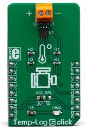
Temp-Log 6 click uses an I2C interface to communicate with the host MCU. It is equipped with an SMD jumper labeled as VCC SEL. This jumper is used to select the power supply for the pull-up resistors on the I2C bus, allowing both 3.3V and 5V MCUs to be interfaced with this Click board™.
Specifications
| Type |
Temperature |
| Applications |
It can be used in many applications, including dual-zone thermal monitoring in FPGA, embedded, and PC systems, i.e. when it is required to monitor both the ambient temperature within the enclosure, as well as the IC die temperature, for test and measurement applications, and similar. |
| On-board modules |
MAX6642, a ±1°C, SMBus/I2C compatible local/remote temperature sensor with an overtemperature alarm, produced by Maxim Integrated. |
| Key Features |
A very high measurement accuracy and repeatability, ALARM thresholds, a dedicated ALARM interrupt pin, dual zone thermal monitoring (ambient temperature and remote temperature), suitable to be used for the on-chip PN junctions, etc. |
| Interface |
I2C |
| Input Voltage |
3.3V or 5V |
| Click board size |
M (42.9 x 25.4 mm) |
Pinout diagram
This table shows how the pinout on Temp-Log 6 click corresponds to the pinout on the mikroBUS™ socket (the latter shown in the two middle columns).
| Notes |
Pin |
 |
Pin |
Notes |
|---|
| |
NC |
1 |
AN |
PWM |
16 |
NC |
|
| |
NC |
2 |
RST |
INT |
15 |
INT |
Alert OUT |
| |
NC |
3 |
CS |
RX |
14 |
NC |
|
| |
NC |
4 |
SCK |
TX |
13 |
NC |
|
| |
NC |
5 |
MISO |
SCL |
12 |
SCL |
I2C Clock |
| |
NC |
6 |
MOSI |
SDA |
11 |
SDA |
I2C Data |
| Power Supply |
3.3V |
7 |
3.3V |
5V |
10 |
5V |
Power Supply |
| Ground |
GND |
8 |
GND |
GND |
9 |
GND |
Ground |
Onboard settings and indicators
| Label |
Name |
Default |
Description |
|---|
| LD1 |
PWR |
- |
Power indication LED |
| JP1 |
VCC SEL |
Left |
Power supply voltage selection: left position 3.3V, right position 5V |
| TB1 |
- |
- |
Remote PN junction connector |
Software support
We provide a library for the Temp-Log 6 click on our LibStock page, as well as a demo application (example), developed using MikroElektronika compilers. The demo can run on all the main MikroElektronika development boards.
Library Description
The library initializes and defines the I2C bus driver and drivers that offer a choice for writing data in register and read data form register. With functions from the library it is possible to read local/remote temperature data and Manifactures ID. The library provides full control of all the registers that the modules contain.
Key functions:
void templog6_writeByte(uint8_t reg, uint8_t _data) - Write functions.uint8_t templog6_readByte(uint8_t reg) - Read function.uint8_t templog6_getAlertState() - ALERT Interrupt state.
Examples description
The application is composed of the three sections :
- System Initialization - Initialization I2C module and sets INT pin as INPUT.
- Application Initialization - Initializes driver init, test comunication and configuration chip for start measurement.
- Application Task - Reads Local and Remote temperature. Temperature data logs to the USBUART every 1sec.
void applicationTask()
{
    uint8_t Remote_Temp;
    uint8_t Local_Temp;
    char demoText[ 50 ];

    Local_Temp = templog6_readByte(_TEMPLOG6_REG_LOCAL_TEMPERATURE);
    IntToStr(Local_Temp, demoText);
    mikrobus_logWrite("--- Local Temperature: ", _LOG_TEXT);
    mikrobus_logWrite(demoText, _LOG_LINE);

    Remote_Temp = templog6_readByte(_TEMPLOG6_REG_REMOTE_TEMPERATURE);
    IntToStr(Remote_Temp, demoText);
    mikrobus_logWrite("--- Remote Temperature: ", _LOG_TEXT);
    mikrobus_logWrite(demoText, _LOG_LINE);

    mikrobus_logWrite("-----------------------------", _LOG_LINE);
    Delay_ms( 1000 );
}
The full application code, and ready to use projects can be found on our LibStock page.
Other mikroE Libraries used in the example:
Additional notes and informations
Depending on the development board you are using, you may need USB UART click, USB UART 2 click or RS232 click to connect to your PC, for development systems with no UART to USB interface available on the board. The terminal available in all MikroElektronika compilers, or any other terminal application of your choice, can be used to read the message.
mikroSDK
This click board is supported with mikroSDK - MikroElektronika Software Development Kit. To ensure proper operation of mikroSDK compliant click board demo applications, mikroSDK should be downloaded from the LibStock and installed for the compiler you are using.
For more information about mikroSDK, visit the official page.