 |
|
|
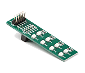
The EasyLED Board is an effective and low-cost solution for visual indication of output signals. LEDs are used for visual indication purposes. This board can be connected to a prototype device via an IDC10 connector.
|
|
|
|
 |

|
|
LED Ring click is a mikroBUS add-on board with a ring of 32 red LEDs driven by four 8-bit 74HC595 serial-in, parallel-out shift registers. The ring is 25mm in diameter. The click communicates with the target MCU through the mikroBUS SPI interface, with RST, CS, SCK, MISO and MOSI pins marked MR#, LAT, CLK, DSOUT, DSIN, respectively. The board is designed to use either a 3.3V or 5V power supply only. |
|
|
|
 |
|
|
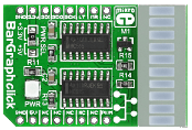
BarGraph Click is a compact and easy solution for adding a ten-segment light bar display to your design. It features the JSB-R102510Z light bar display as well as two 74HC595 shift registers. The 74HC595 IC contains an 8-bit serial in, parallel/serial-out shift register as well as 8-bit storage register. BarGraph Click communicates with the target board microcontroller via mikroBUS SPI (MOSI, MISO, SCK, CS), RST and PWM lines. An SMD jumper is provided which allows the user to select whether the board will be powered with a 3.3V or 5V power supply. |
|
|
|
 |
|
|
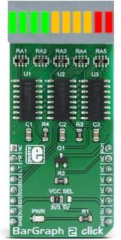
BarGraph 2 click is a 10-segment bar graph display click, which uses a high-quality, multicolor bar graph LED display. The bar graph display is a very popular device for displaying various properties, whether it be an audio level, current/voltage level, position of the encoder, and generally any property that can be displayed in a form of a bar graph. The segments of the onboard bar graph LED display are bright and uniformly colored, providing a nice and clean visual feedback. |
|
|
|
 |
|
|
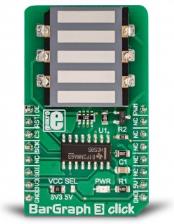
BarGraph 3 click is equipped with a five-segment LED bar graph display, notable for its strong and uniform illumination of the segments. Each segment consists of three internal LEDs with a common cathode, while the anodes of all LEDs are connected in a single point. This reduces the number of the display bar pins to just six. The common anode is connected to the PWM pin of the microbus via the P-type MOSFET, which can use the PWM signal from the microcontroller to change the intensity of the display. The fact that there are as many as three LEDs per segment makes the segments evenly illuminated, and the red color of the light on the dark background makes segments clearly visible.
It comes in the package which also includes the mikroSDK™ software and a library with all the functions. The Click board™ comes as a fully tested and approved prototype, making it a reliable device ready to use on the development board.
|
|
|
|
 |
|
|
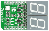
7seg click is an accessory board in mikroBUS form factor. It's a compact and easy solution for adding a 2-digit seven-segment display to your device. It features two 74HC595 8-bit serial-in, parallel-out shift register modules as well as two seven-segment digits. 7seg Click communicates with target boards via an SPI interface. It has a green LED which indicates the presence of power. An SMD jumper is available for selecting whether the board will be operating on a 3.3V or 5V power supply. |
|
|
|
 |

|
|
BIG 7-SEG R click is what you need if you want to add a seven-segment LED display to your project. This click features an SC10-21SRWA seven-segment display. |
|
|
|
 |

|
|
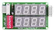
The Serial 7-seg Display Board features the MAX7219 compact, serial input/output, common-cathode display driver - used to interface MCUs to 7-segment numeric LED displays via SPI interface. The chip includes a BCD code-B decoder, multiplex scan circuitry, segment and digit drivers and 8x8 static RAM for storing digits. Display drivers are connected to 4 common-cathode LED displays. The board features four 7-segment digits arranged in a single row. |
|
|
|
 |
|
|
The Serial 7-seg Display 2 Board enables you to use a 7-segment LED display. It features an on-board SPI interface, LED display driver MAX7219 and 8 common-cathode LED displays. The board is connected to a device via an on-board IDC10 connector. |
|
|
|
 |

|
|
The Serial 7-seg Display - 8-Digit Board features the MAX7219 compact, serial input/output, common-cathode display driver - used to interface MCUs to 7-segment numeric LED displays via SPI interface. The chip includes a BCD code-B decoder, multiplex scan circuitry, segment and digit drivers and 8x8 static RAM for storing digits. Display drivers are connected to 8 common-cathode LED displays. The board features eight 7-segment digits arranged in a single row. |
|
|
|
 |
|
|
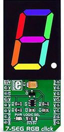
7-SEG RGB click carries a full color single 7 segment digit display. The click is designed to run on either 3.3V or 5V power supply. It communicates with the target microcontroller over the CS, and PWM pin on the mikroBUS™ line. |
|
|
|
 |
|
|
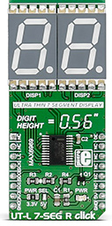
Add a double 7 segment display to your next project.
UT-L 7-SEG R click carries two SMD ultra thin LED 7-SEG displays and the MAX6969 constant-current LED driver from Maxim Integrated. The click is designed to run on either 3.3V or 5V power supply. It communicates with the target microcontroller over SPI interface. |
|
|
|
 |
|
|
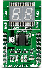
Add a double 7 segment display to your next project.
UT-M 7-SEG R click carries two SMD ultra thin LED 7-SEG displays and the MAX6969 constant-current LED driver from Maxim Integrated. The click is designed to run on either 3.3V or 5V power supply. It communicates with the target microcontroller over SPI interface. |
|
|
|
 |
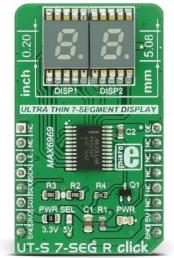
|
|
7-segment LED display is the most commonly used type of display to represent changing numerical values. The principle is very simple - seven LED segments are positioned in a certain shape and by turning specific segments on or off, the shape that resembles a specific number is lit. This method of displaying numbers was first used in the beginning of the 20th century, but after the invention of the LED in '70, it is the most commonly used method to display numbers. It utilizes a fairly simple and cheap design with the numbers clearly visible. Be it a clock on the nightstand, a billboard at the airport, a gauge on some machine, a panel on some instrument or a display on the pump at the gas station - the numbers will be always easy to see and read, even in the dark.
UT-S 7 SEG R click uses two SMD ultra-thin DSM7UA20101 7-SEG LED displays, made with the patented technology that delivers thickness of only 2.1 mm. These displays are driven by the MAX6969, a constant current LED integrated driver from Maxim Integrated, which uses the SPI serial interface for communication and delivers steady and constant power source for the LED segments. |
|
|
|
 |

|
|
AlphaNum click is a simple solution for adding 14-segment alphanumeric display to your device. The board carries two TLC5926 16-bit Constant-Current LED sink Drivers as well as a dual character green or red LED 14-segment display (with two additional segments for commas). AlphaNum click communicates with the target board through mikroBUS RST, CS, SCK, MISO, MOSI, PWM and INT pins (marked here as LE2, LE1, CLK, DOUT, DIN, NUMSEL and NUMSEL respectively). The board is designed to use either a 3.3V or 5V power supply.
|
|
|
|
 |

|
|
7x10 R click carries a matrix of 70 red LEDs driven by a pairs of 8-bit serial-in, parallel-out shift registers, a Darlington Transistor array and a Johnson counter. 7x5 is a standard resolution for displaying ASCII characters, so 7x10 click is essentially a dual-character display capable of showing letters in more readable typefaces compared to a 14-segment display. The click communicates with the target MCU through the mikroBUS SPI interface (SCK, SDO, SDI), with additional functionality provided by R CLK, MR#, LATCH and R RST pins. 7x10 R click is designed to use either a 3.3V or a 5V power supply. |
|
|
|
 |

|
|
Matrix click is a mikroBUS add-on board with two 5x7 matrices driven by two MAX7219 8-bit LED Display Drivers. The active area of each matrix is 7.62mm high and 5.08 mm wide. 7x5 is a standard resolution for displaying ASCII characters, so the click is essentially a dual-character display capable of showing letters in more readable typefaces compared to a 14-segment display. The click communicates with the target MCU through the mikroBUS SPI interface with two separate Chip Select lines for each matrix (CSL for the left, CSR for the right). This board is designed to use a 5V power supply. |
|
|
|
 |

|
|
8x8 R Click is an add-on board in the mikroBUS form factor. It's a compact and easy solution for adding an 8x8 LED matrix display to your design. It features the MAX7219 8-digit LED display driver module as well as 64 LED diodes. 8x8 Click communicates with the target microcontroller via four SPI lines (DIN, DOUT, CLK and CS). The board is designed to be powered by 5V, but can also communicate with 3.3V MCUs. |
|
|
|
 |

|
|
16x9 G click contains a green LED matrix and the IS31FL3731 audio modulated matrix LED driver. The dimension of the LED matrix is 16x9. Each LED can be controlled individually – both for on/off control and light intensity. The click is designed to run on either 3.3V or 5V power supply. It communicates with the target microcontroller over I2C interface. |
|
|
|
 |
|
|
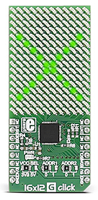
Add a green LED display to your design.
16x12 G click carries a 16x12 LED display and the IS31FL3733 matrix driver. The click is designed to run on either 3.3V or 5V power supply. It communicates with the target microcontroller over I2C interface, and the following pins on the mikroBUS™ line: INT, RST, CS. |
|
|
|
 |

|
|
7x10 G click can be used for displaying letters on a display with 7x5 font resolution. It carries a matrix of 70 green LEDs driven by a pair of 8-bit serial-in, parallel-out shift registers, a Darlington Transistor array and a Johnson counter.
7x10 G click is designed to run on either 3.3V or 5V power supply. It communicates with the target microcontroller over SPI interface, with additional functionality provided by the following pins on the mikroBUS™ line: AN, PWM, RST. |
|
|
|
 |
|
|
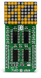
70 super bright yellow LEDs for displaying the most versatile set of symbols and characters
7x10 Y click displays letters, numbers, and characters in a 7x5 font resolution. It carries a matrix of 70 yellow LEDs driven by a pair of 8-bit serial-in, parallel-out shift registers, a Darlington Transistor array and a Johnson counter.
The display has the capability to scroll the text across the screen. |
|
|
|
 |
|
|
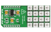
4x4 RGB click carries a matrix of 16 WS2812 RGB LEDs and a MCP1826 low dropout regulator. These LEDs actually consist of three single colored LEDs (Red, Green and Blue), plus a control chip in a single package; various colors can be reproduced by mixing the intensity of each LED. However, don't drive the LEDs to maximum brightness because it will generate excessive heat and draw more current that advisable (up to 0.7A) which could potentially damage the mainboard. Also, don't touch the board when it's in use. The LED matrix is connected to the target board microcontroller through the mikroBUS RST pin. The board uses either a 3.3V or 5V power supply. |
|
|
|
 |
|
|
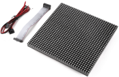
Hi-brightness RGB LED matrix panel, with 1024 RGB LEDs arranged in a 32x32 grid on the front. Comes with one IDC cable and a power cable.
The panel is driven by shift registers, for more information please see the Learn Article. |
|
|
|
 |
|
|
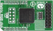
Matrix RGB click is a mikroBUS add-on board powered by a 32-bit FT900 MCU designed specifically for powering 16x32 RGB LED matrices.
The board has a 16 wire IDC connector for connecting to a single 16x32 LED panel, however, the firmware inside the FT900x chip can drive more than one panel.
Multiple panels can be connected to each other into a daisy-chain configuration (see the video). Matrix RGB click communicates with the target MCU through the SPI interface. It uses a 3.3V power supply only.
Complete kits with Matrix RGB click, a single 32x32 RGB LED matrix panel (consisting of two 16x32 matrices joined together), and a power supply unit are available to order.
Alternatively, panels and power supplies can be purchased separately. |
|
|
|
 |
|
|
 |
|
|
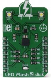
LED Flash 2 click is a powerful flash/torch click, featuring the MIC2870 from Microchip, a high-efficiency flash LED driver, optimized for driving one or two high-brightness camera flash LEDs. The MIC2870 IC can drive one high brightness LED up to 1.5A or two high brightness LEDs, up to 750mA each. Two high brightness LEDs are already mounted on the Led Flash 2 click, so the click board is ready to be used right away.
LED Flash 2 click provides two modes of operation - the Torch mode and the Flash mode. While working in Torch mode, the output current is adjusted so that the continuous operation of the LEDs is provided. When it is set to work in the Flash mode, the LED current is maximized and while giving a powerful light, it can not work for prolonged periods. The Torch mode will turn the click board™ into a simple handheld torchlight, while the Flash mode is good for using the LEDs as the camera flash, providing good images in various low light situations. |
|
|
|
 |
|
|
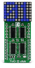
70 super bright blue LEDs for displaying the most versatile set of symbols and characters
7x10 B click displays letters, numbers, and characters in a 7x5 font resolution. It carries a matrix of 70 blue LEDs driven by a pair of 8-bit serial-in, parallel-out shift registers, a Darlington Transistor array and a Johnson counter.
The display has the capability to scroll the text across the screen. |
|
|
|
 |
|
|
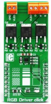
RGB Driver click is an RGB LED driver, capable of driving RGB LED stripes, LED fixtures and other RGB LED applications that demand an increased amount of current and voltage. Besides the NCP5623B IC, a triple output RGB LED driver IC which uses I2C interface for the communication with a microcontroller (MCU), this Click board™ is equipped with three additional Power MOSFETs with very low RDSON value, which allow this IC to drive power demanding RGB elements, such as the LED strips, LED spotlights and similar RGB LED installations. The IC itself is capable of displaying a large palette of colors with 32 steps for each of the R, G, and B channels. |
|
|
|
 |
|
|
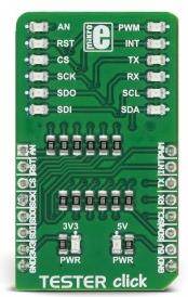
Tester click is a Click board™ used as a diagnostic tool on the mikroBUS™ socket. It contains an array of 2x6 LEDs, which signalize the presence of the HIGH/LOW logic level on each pin, providing a visual feedback to the developer. Two additional LEDs indicate the presence of +3.3V and +5V on the mikroBUS™ power rails. This simple diagnostic tool can save hours of troubleshooting, saving the application developer from having to connect various complicated measurement instruments, only to test logic states on the specific mikroBUS™ pins. |
|
|
|
 |
|
|
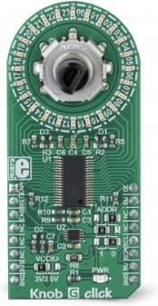
Knob G click features a combination of high-quality quadrature rotary encoder, and a LED ring composed of 24 individual green LEDs. Outputs of the rotary encoder are processed by a debouncing circuitry, which ensures reliable switching action, making the encoder directly usable in interrupt service routines (ISR) without the need for a bulky debouncing code. The 24-segment LED ring is driven by an advanced and flexible LED driver IC, which can dim each LED individually, allowing various lighting effects to be programmed. The LED ring is independent of the encoder, and it can be used as a very flexible position or value indicator.
Knob G click is supported by a mikroSDK compliant library, which includes functions that simplify software development. This Click board™ comes as a fully tested product, ready to be used on a system equipped with the mikroBUS™ socket.
|
|
|
|
 |
|
|
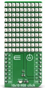
10x10 RGB Click is a matrix of 100 "intelligent" RGB elements, forming a 10x10 display screen. These LED elements feature internal logic, which allows them to communicate directly with the MCU. These intelligent LEDs are meant to be cascaded: the elements communicate by a single line with the host MCU and they feature a signal reshaping section, so the data gets to the adjacent element with no losses or distortion.
10x10 RGB Click is supported by a mikroSDK compliant library, which includes functions that simplify software development. This Click board™ comes as a fully tested product, ready to be used on a system equipped with the mikroBUS™ socket.
|
|
|
|
 |

