 |
|
|
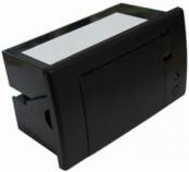
The CSN-A2 thermal printer is similar to what you would find on a credit-card POS machine. With a simple serial UART (TTL) interface, this unit has the ablity to print strings and bitmap images, as well as generate several different formats of barcodes. It uses a 12V power supply with the maximun current draw of 1.5A.
Printing speed is 50-80mm/s, with a resolution of 8 dots per millimetre (around 384 dots per line) and an effective printing width of 48mm.
The thermal paper that is used in the printer is commonly found in most office supply stationary stores and is sized at 57mm ±0.5mm thick, with a maximun paper roll diameter of 39mm (larger rolls can be made smaller to fit by simply removing some extra paper - this paper can then still be used in the unit, as one does not need to use a 'core' in the paper for it to work with the thermal printer).
|
|
|
|
 |
|
|
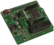
Breeze boards are versatile development boards for 28-pin PIC microcontrollers. Use them for learning, for rapid prototyping of your next project, or as the core board in your final product.
The Breeze A includes a USB-UART converter, for easy serial communication with a computer. |
|
|
|
 |
|
|
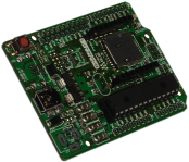
Breeze boards are versatile development boards for 28-pin PIC microcontrollers. Use them for learning, for rapid prototyping of your next project, or as the core board in your final product.
The Breeze B includes a microcontroller with built-in USB support. |
|
|
|
 |
|
|
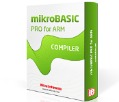
Write fast multimedia applications for mighty ARM Cortex M0, M3 and M4 devices using mikroBasic programming environment.
|
|
|
|
 |
|
|
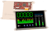
Intelligent
7" TFT display with 800x480px resolution, optional resistive or capacitive touch-screen, as well as bezel and super-bright options, featuring the DIABLO controller as well as a number of other features.
Please note that extended lead-time / MOQ may be applicable for some variants - please contact us for more information. |
|
|
|
 |
|
|
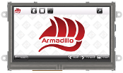
The Armadillo-43 is a complete Linux based computer module with a built-in 480x272 TFT LCD display.
The board is designed to be a Raspberry Pi with built-in display, and features the same Broadcom BCM2835 System-On-Chip (SoC) which is found on the Pi. |
|
|
|
 |

|
|
The 4DCAPE-70T is a 7" TFT display, with 800x480px resolution and resistive touch-screen, specifically designed for the Beagle Bone Black. |
|
|
|
 |

|
|
3G-EA click is a versatile cellular network communication solution, featuring the compact 3G UMTS/HSPA Quectel UG95 module. This module features a full set of options for the cellular networking and communication, such as the network indication, embedded TCP/UDP stack, HTTP/HTTPS stack, full GSM/GPRS/EDGE implementation, UMTS/HSDPA/HSUPA protocol implementation and more. 3G-EA click features data-rates of 7.2 Mb/s (downlink) and 5.76 Mb/s (uplink) in HSPA mode. Onboard 16bit audio CODEC IC adds high-quality voice communication capability.
|
|
|
|
 |
|
|
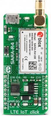
LTE IoT click is a Click board™ that allows connection to the LTE and 2G networks, featuring the compact form-factor SARA-R410M-02B LTE/2G module, which offers two LTE technologies aimed at Machine to Machine communication (M2M) and the Internet of Things (IoT). This module is an embedded IoT communication solution which supports the LTE Cat M1 and NB1 technologies, offering an alternative to similar Low Power Wide Area Network (LPWAN) solutions, such as the ones provided by Sigfox and LoRa. The LTE CAT1 and NB1 technologies are designed with specific requirements of the IoT network in mind. LTE IoT click also offers various other features, allowing simple and reliable connection to these new 3GPP IoT technologies. |
|
|
|
 |
|
|
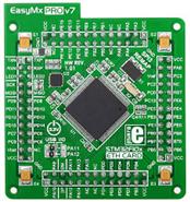
Note: Image is representative of product range - individual products may differ slightly. |
|
|
|
 |
|
|
 |
|
|
 |
|
|
Intelligent
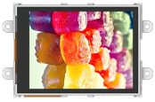
2.8" TFT display with 320x240px resolution and resistive touch-screen, featuring the PICASO controller as well as a number of other features. |
|
|
|
 |
|
|
Intelligent
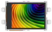
2.4" TFT display with 320x240px resolution and resistive touch-screen, featuring the PICASO controller as well as a number of other features. |
|
|
|
 |
|
|
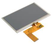
FRD070IF40-A-T
800 x 480 pixels
Resistive Touch Screen
Module Size: 165 x 100mm
Viewing Area: 153.6 x 86.6mm |
|
|
|
 |
|
|
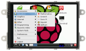
The 4DPi is a display board for the Raspberry Pi, which plugs directly on top of a Raspberry Pi and displays the primary output which is normally sent to the HDMI or Composite output of the Pi. It comes in either a 3.2" 320x240 or 3.5" 480x320 version, with both versions featuring a resistive touch-panel. |
|
|
|
 |
|
|
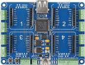
Quail is an STM32-powered development solution for building hardware prototypes with click boards and C# managed code. It brings together click boards and Microsoft's .NET Micro Framework for embedded devices (NETMF). Write code for your Quail projects in Microsoft Visual Studio (free in the community edition); drivers for individual click boards are provided by the MikroBUS.NET team. Hardware-wise, Quail has 4 mikroBUS sockets for click board connectivity, along with 24 screw terminals for connecting additional electronics and two USB ports (one for programming, the other for external mass storage). The board runs on a 5V power supply. |
|
|
|
 |
|
|
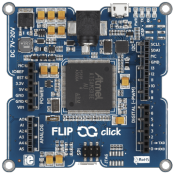
Flip & click is like an Arduino on one side, but with the added functionality of four mikroBus sockets on the other. This makes it easy for users familiar with Arduino to include functionality from the huge range (160+) of click boards in their designs. The board features an AT91SAM3X8E microcontroller (the same MCU as found on the Arduino Due), the familiar Arduino Uno pinout, and the four mikroBus sockets on the back. In addition to this, four LEDs and a USB host/device connector are also included. |
|
|
|
 |
|
|
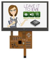
The 4DLCD-FT843 features a 4.3" display with resistive touch panel, and integrated FTDI FT800 Video Engine with SPI interface. The FT800 is like a "graphics card" for microcontrollers - it offloads all the work of running a display to a separate, fast and powerful controller, making it possible to have great graphics with low-cost microcontrollers.
Note: This product uses an FFC connector. You will need either a matching connector on your board, or a breakout board, in order to connect to the display. |
|
|
|
 |
|
|
Note: Image is representative of product range - individual products may differ slightly. |
|
|
|
 |
|
|
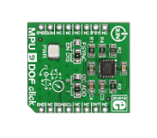
MPU 9DOF click carries the MPU-9150 System in Package, which is the world's first 9-axis Motion Tracking device. MPU-9150 comprises two chips. One is the MPU-6050 that contains a 3-axis accelerometer, a 3-axis gyroscope, and a DMP (digital motion processor); the other is AK8975, a 3-axis digital compass. The MPU-9150 is designed for the low power, low cost, and high performance requirements of consumer electronics equipment and wearable sensors. The ability to track motion in free space also makes MPU 9DOF click a suitable sensor for RC vehicle (e.g. quadcopters) and camera stabilisation systems. |
|
|
|
 |
|
|
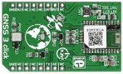
GNSS3 click carries SIMCom's SIM33ELA standalone GNSS module with an integrated antenna (as well as a connector for an external one). GNSS stands for Global Navigation Satellite System, an umbrella term that describes both the United States GPS and the Russian GLONASS global positioning systems. The SIM33ELA module has MTK's high sensitivity navigation engine. It features EPO orbit prediction, AGPS and SBAS ranging (WAAS, EGNOS, GAGAN, MSAS). GNSS3 click communicates with the target MCU through mikroBUS UART pins (RX, TX), with additional functionality provided through RST and INT pins. The board uses a 3.3V power supply. |
|
|
|
 |
|
|
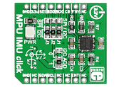
MPU IMU click carries the MPU-6000 integrated 6-axis motion tracking device, which combines a 3-axis gyroscope, 3-axis accelerometer, and a DMT (Digital Motion Processor) into a single small chip. The gyroscope has a sensitivity up to 131 LSBs and a full-scale range of ±250, ±500, ±1000, and ±2000dps. The accelerometer has a programmable full scale range of ±2g, ±4g, ±8g and ±16g. It communicates with the target board through SPI, I2C, RST and INT lines. The board is designed to use a 3.3V power supply only. An LED diode serves as a power indicator. |
|
|
|
 |
|
|
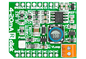
4-20mA R Click is an add-on board in mikroBUS form factor which serves as a receiver in a 4-20mA current loop standard. It features INA196 current shunt monitor, MCP3201 12-bit ADC as well as the TPS61041 DC/DC boost converter. It receives output current (4-20mA) from the transmitter and converts it into a voltage (0.4-2V). This voltage is converted into a 12-bit data signal in the MCP3201 A/D converter and sent via mikroBUS SPI lines. Together with 4-20mA T Click this board forms a complete 4-to-20mA current loop standard. It is designed to use either a 3.3V or 5V power supply. |
|
|
|
 |

|
|
Hall current click is a high precision current sensor. It carries a galvanically isolated TLI4970-D050T4 miniature magnetic digital current sensor that utilizes the Hall effect to measure electric current. It can detect current levels from -49 to +49 amps, both AC and DC. The board carries two EXTreme ZPower connectors (IP- and IP+) to connect the conductor. The current rail is galvanically isolated from the interface to the microcontroller. The sensor readings are sent to the target board through the mikroBUS SPI (SDO, SCK, and CS) lines. The board uses a 3.3V power supply only.
Hall current click can be used with dangerous voltage levels. Use caution when working with current and the Hall current click - DO NOT TOUCH THE BOARD WHILE THE EXTERNAL POWER SUPPLY IS ON! |
|
|
|
 |

|
|
4-20mA T Click is an add-on board in mikroBUS form factor. It's a compact and easy solution for adding an industry standard 4-to-20mA current loop communication protocol to your design. It features the ADuM1411 quad-chanel digital isolator, MCP4921 12-bit DAC as well as the XTR116 4-20mA current loop transmitter. The board communicates with the microcontroller via three SPI lines (SDI, SCK and CS). The board can be used with either a 3.3V or 5V power supply. An LED indicates the presence of power supply to the board. |
|
|
|
 |
|
|
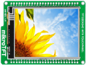
mikroTFT is a breakout board for MI0283QT-9A 2.8" TFT color display with 320 x 240 pixel resolution, driven by ILI9341 display controller. TFT display is covered with a resistive touch panel which can be used as an input device. For further connectivity two 1x26 side headers are provided. Mounting holes (∅ 2.29 mm) located in each corner simplify integration. Board is designed in the same form factor as mikromedia boards. This allows you to easily switch from mikroTFT to mikromedia, and vice-versa, while retaining most of the integration features. |
|
|
|
 |
|
|
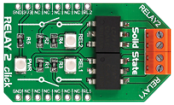
Relay 2 click carries two LCA717 single-pole, OptoMOS solid state relays and two screw terminals for connecting the wiring. These relays have a load current of 2A, low maximum on-resistance of just 0.15 Ohms, and a blocking Voltage of 30V. The LCA717 have optically coupled outputs that use the patented OptoMOS technology. Solid state relays enable fast, silent and bounce-free switching. Each relay is coupled with an onboard signal LED. The board is designed to use a 3.3V power supply only. |
|
|
|
 |
|
|
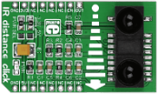
IR distance click carries Sharp's GP2Y0A60SZ0F distance measuring sensor. The sensor module comprises an integrated PSD (position sensitive detector), an infrared LED and a signal processing circuit. The measuring range is between 10 and 150 cm. The sensor is not easily influenced by the reflectivity of the object, but it's important to keep the lens clean. The click board outputs an analog voltage corresponding to the distance of the object (through the mikroBUS AN pin). An Enable (EN) pin is also utilized. The board is designed to use either a 3.3V or a 5V power supply. |
|
|
|
 |
|
|
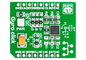
Gyro Click is an add-on board in the mikroBUS form factor. It features the L3GD20 three-axis digital gyroscope module, which is capable of providing the measured angular rate as well as the ambient temperature. The L3GD20 has a full scale of ±250 / ±500 / ±2000 dps and is capable of measuring rates with a user-selectable bandwidth. Gyro Click communicates with the target board microcontroller via mikroBUS SPI (MOSI, MISO, SCK, CS), I2C (SDA, SCL), INT and RST lines. The board is designed to use a 3.3V power supply only. All these features make this board ideal for gaming and virtual reality input devices, motion control, GPS navigation systems and more. |
|
|
|
 |
|
|
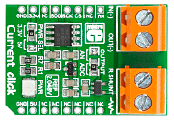
Current Click is an add-on board used for the measurement of electric current. It features an INA196 current shunt monitor, MCP3201 12-bit ADC, MAX6106 voltage reference as well as two screw terminals. The board receives current from the output circuit connected to IN(+) and OUT(-) pins of the first screw terminal connectors. INA196 IC converts this current into a voltage. The second screw terminal is used for external shunt. In order to measure current values in various bands, you need to provide the shunt of the appropriate value. Four shunts with different values are provided in the package. Current Click communicates with the target microcontroller via mikroBUS SPI or AN lines. The board is designed to work with either a 3.3V or 5V power supply. |
|
|
|
 |
|
|
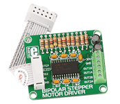
The Bipolar Stepper Motor Driver Board enables you to add stepper motor control to your applications. There is an on-board microstepping motor driver A3967SLB. The board supports Mixed, Fast and Slow Current-Decay Modes. |
|
|
|
 |
|
|
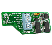
The SerialRAM Board enables you to use a 64Kbit Serial SRAM device with your development board. The board features the 23K640 Serial RAM device that communicates with microcontrollers via a Serial Peripheral Interface (SPI). |
|
|
|
 |

|
|
RS485 2 click carries the MAX3471 half-duplex transceiver intended for lithium battery-powered RS-485/RS-422 applications.
The click is designed to run on either 3.3V or 5V power supply. It communicates with the target microcontroller over UART interface with additional functionality provided by the following pins on the mikroBUS™ line: PWM, CS. |
|
|
|
 |

|
|
PIC clicker is a compact and cost-effective board, featuring the PIC18F47J53 microcontroller as well as a mikroBus socket for easily connecting "click" accessory boards (3.3V I/O levels). It also features a USB connector, two LEDs and two push buttons, mikroProg programming connector and an expansion header. The board comes pre-loaded with a fast USB HID bootloader. |
|
|
|
 |
|
|
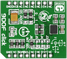
9DOF click carries ST's LSM9DS1 inertial measurement module that combines a 3D accelerometer, a 3D gyroscope and a 3D magnetometer into a single device outputting so called nine degrees of freedom data (3-axis acceleration, angular velocity and heading), in 16-bit resolution. 9DOF click communicates with the target MCU through the mikroBUS I2C interface (SCL and SDA) with additional functionality provided by the programmable Interrupt (INT) pin, as well as the Enable (EN) pin. The IC has multiple interrupt lines which can be accessed through jumpers on the click board. I2C addresses are specified in the same manner. The board uses a 3.3 power supply only. |
|
|
|
 |

|
|
ETH Wiz click carries W5500, a 48-pin, 10/100 BASE-TX standalone ethernet controller with a hardwired TCP/IP Internet protocol offload engine, along with a standard RJ-45 connector. The W5500 module employs a variety of solutions to reduce the target MCU's memory load and enable a stable and secure Internet connection. High speed network communications are realized through an 80 MHz SPI interface. The module has 32KB of internal memory for TX/RX buffers. Reduced power consumption is achieved with Wake on LAN and power down modes. Automatic handshaking, retransmit on collision and automatic rejection of erroneous packets are also supported. |
|
|
|
 |
|
|
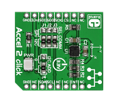
Accel 2 click carries ST's LIS3DSH IC, a low-power factory-calibrated three-axis accelerometer which embeds a FIFO buffer and two programmable state machines. It allows you to implement gesture recognition. User-defined programs can distinguish movement patterns like shake and double shake, face up and face down, turn and double turn, and activate an interrupt upon their execution. You can also switch between I2C and SPI interfaces for communicating with the target board MCU (by soldering the onboard jumpers in the appropriate positions). Accel 2 click is designed to use a 3.3V power supply only. |
|
|
|
 |
|
|
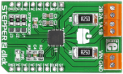
Stepper 2 click carries a A4988 microstepping motor driver along with screw terminals for connecting a motor and a required external power supply (minimum 7V). The output drive capacity of the motor is up to 35V and ±2A. The A4988 chip is designed to drive bipolar stepper motors in full-, half-, quarter-, eight-, and sixteenth-step modes. A set of three onboard jumpers (J1-J3) allow you to switch between the different stepping modes. The board communicates with the target MCU through EN, RST, SL, ST and DIR pins (corresponding to AN, RST, CS, PWM and INT pins of the default mikroBUS configuration). Stepper 2 click can use both a 3.3V and 5V power supply. |
|
|
|
 |
|
|
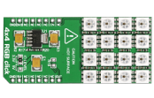
4x4 RGB click carries a matrix of 16 WS2812 RGB LEDs and a MCP1826 low dropout regulator. These LEDs actually consist of three single colored LEDs (Red, Green and Blue), plus a control chip in a single package; various colors can be reproduced by mixing the intensity of each LED. However, don't drive the LEDs to maximum brightness because it will generate excessive heat and draw more current that advisable (up to 0.7A) which could potentially damage the mainboard. Also, don't touch the board when it's in use. The LED matrix is connected to the target board microcontroller through the mikroBUS RST pin. The board uses either a 3.3V or 5V power supply. |
|
|
|
 |
|
|
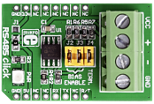
RS485 Click is an accessory board in mikroBus form factor. The on-board SN65HVD12 (3.3V) or ADM485 (5V) differential line transceiver is suitable for high speed bidirectional data communication on multipoint bus transmission lines. It is designed for balanced data transmission and complies with EIA standards RS-485 and RS-422. This transceiver features a differential line driver and differential line receiver. |
|
|
|
 |

|
|
The mikroDrive board features the high-current ULN2803 darlington-transistor array IC, with the ability to drive up to 8 external loads. A jumper is provided for power-supply selection between an external power source or microcontroller VCC. The board provides an interface between low-level microcontroller logic circuitry and external power loads. |
|
|
|
 |
|
|
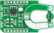
LIN HALL click carries an MLX90242 linear Hall sensor IC (with built-in active error correction circuitry) and an MCP3201 12-bit ADC. It outputs a signal that is proportional to the flux density of a magnetic field - a north magnetic field will increase the output value while a south magnetic field will cause it to decrease. The ratiometric output allows you to infer the linear or rotary position of a target object by placing magnets on it. LIN HALL click communicates with the target board through the mikroBUS SPI lines (CS, CSK, MISO). The board is designed to use either a 3.3V or a 5V power supply. |
|
|
|
 |
|
|
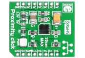
Proximity click features a VCNL4010 proximity and ambient light sensor. It combines an infrared emitter and PIN photodiode for proximity measurement with a range of up to 20cm. The VCNL4010 has a 16bit resolution which ensures excellent cross talk immunity. It can also be used as an ambient light sensor. Proximity click communicates with the target board microcontroller via mikroBUS I2C (SDA, SCL) and INT lines. The board is designed to use 3.3V power supply and 3.3V or 5V I/O voltage levels. |
|
|
|
 |
|
|
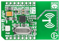
nRF T Click is an add-on board in the mikroBUS form factor. It features the Nordic nRF24L01P 2.4 GHz transceiver module with an embedded baseband protocol engine as well as 2.4 GHz PCB trace antenna. The board supports an air data rate of 250 Kbps, 1 Mbps and 2 Mbps and it is suitable for ultra low power designs. Typical applications include wireless PC peripherals, remotes, VoIP headsets, game controllers, sensors, home and commercial automation, active RFID, toys, etc. nRF C Click communicates with the target board microcontroller via mikroBUS SPI (SDI, SDO, SCK, CS#), CE and INT lines. The board is designed to use a 3.3V power supply only. |
|
|
|
 |

|
|
CapSense click features the CY8C201A0 capacitive sensing module, which takes human body capacitance as an input and directly provides real time sensor information output via I2C. The board contains capacitive sensing elements (5-segment slider and two buttons) as well as two LEDs. The CY8C201A0 capacitive controller has high immunity against radiated and conductive noise. The board can operate at either 3.3V or 5V, with selection by means of SMD jumper. |
|
|
|
 |
|
|
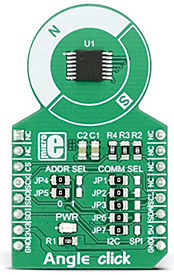
Angle click is a precise Hall-effect angle sensing click board that can be used to measure the rotational angle of the magnetic field in the X-Y plane above it (parallel to the surface of the click), through the whole range of 360°. The click yields very precise results for both off-axis and axis operation, which make it a perfect choice for precise measuring of the rotational angle in a wide range of different high-speed applications, for example in the automotive industry: electronic power steering, transmission, torsion bar, or the motor shaft rotation.
Angle click features the A1335 Hall-effect angle sensing IC, made by Allegro MicroSystems LLC. This IC measures the magnetic field angular vector, based on the actual physical reading of the integrated Hall-effect sensor, as well as the user selected parameters, such as the digital filtering, dynamic range and scaling. The integrated 32bit MCU ensures that the processed data is delivered with a minimal delay and it has enough power to provide the complex processing of the input values so that the measurement remains fast, precise and linear. |
|
|
|
 |
|
|
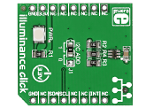
Illuminance click carries a TSL2561 light-to-digital converter with a sensor that's designed to mimic the way humans perceive light. This makes it ideal for applications where ambient lighting conditions have to be measured (backlight power-saving on LCD displays for example). The sensor has two photodiodes. One sensitive to full-spectrum light, the other to infrared. The visible-spectrum is then deduced by using a formula. Illuminance click communicates with the target board through mikroBUS I2C lines, and uses a 3.3V power supply. |
|
|
|
 |
|
|
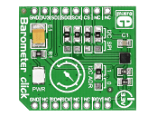
Barometer click carries the LPS25HB IC, which is a piezoresistive absolute pressure sensor with a measurement range from 260 to 1260 hPa (with a 24-bit resolution output). It's a high precision sensor and high resolution mode it can measure pressure within 0.01 hPa RMS. A low resolution mode can be implemented to reduce power consumption. Barometer click can communicate with the target board MCU either through I2C or SPI pins (which is specified by soldering onboard jumpers in appropriate position). An interrupt pin is also available, which can be configured either as Data Ready (sends signal when pressure value changes) or as a threshold trigger (sends signal when specified high or low pressure value is reached). The board uses a 3.3V power supply only. |
|
|
|
 |

|
|
Display bezel for pre-gen4-series 4D Systems displays. Facilitates easy and attractive panel-mounting.
Includes mounting spring-clips, screws and washers. |
|
|
|
 |
|
|
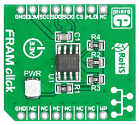
FRAM click brings 256Kbit (32,768 words x 8 bits) of Ferroelectric Random Access Memory to your design. It features the MB85RS256A module which uses the ferroelectric process and silicon gate CMOS technologies for forming the nonvolatile memory cells. It is able to retain data without using a back-up battery. The memory can be used for 10 bilion read/write operations and does not take long time to write data unlike Flash memories or EEPROM. It uses SPI to communicate with the target device. Maximum operating frequency is 25MHz. The board is designed to use 3.3V power supply only. |
|
|
|
 |
|
|
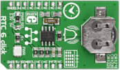
RTC6 click carries Microchip's MCP79410 Real-Time Clock/Calendar IC with built-in 64 bytes of battery-backed SRAM an additional 1 Kbit of EEPROM. 64 bits of protected EEPROM requires an unlock sequence to be unlocked, which makes it suitable for storing a unique ID or other critical information. RTC6 click tracks hours, minutes, seconds, days, months, years and weekdays, with leap year compensation until the year 2399. The clock frequency is derived from an onboard 32.768KHz crystal oscillator. Backup power is supplied by a coin-cell Lithium battery. RTC6 communicates with the target board MCU through the mikroBUS I2C interface (SCL, SDA) along with a multifunction pin (MFP, in place of default mikroBUS INT pin). The multifunctional pin (MFP) can be configured as an alarm, a square wave frequency output, or a general purpose output. The board is designed to use either a 3.3V or a 5V power supply. |
|
|
|
 |
|
|
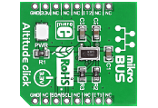
Altitude click features the MPL3115A2 MEMS pressure sensor, which provides accurate pressure/altitude (20-bit) and temperature (12-bit) data. Resolution is down to 30 cm (1.5 Pa). The MPL3115A2 contains automatic internal data processing with data acquisition and compensation. It features a 32 sample FIFO buffer to minimize the overhead of collecting multiple data samples. It can autonomously collect data at programmed intervals and store it up to 12 days depending on data acquisition rate (1 second - 9 hours). The board uses an I2C communication interface and is designed to use a 3.3V power supply only. |
|
|
|
 |

|
|
MCP2542 click is a mikroBUS add-on board with a Microchip CAN FD Transceiver with Wake-Up Pattern. The physical layer is compliant with CAN 2.0 and CAN with Flexible Data Rate (CAN FD). It is designed specifically for high-speed CAN FD applications with communication speeds of up to 8 Mbps. Longer than usual BUS lengths are supported thanks to the improved maximum propagation delay.
The board has a standard RS232 port for CAN communications.
MCP2542 click communicates with the target board MCU through mikroBUS UART interface with an additional StandBy pin (STBY, in place of default mikroBUS AN pin). Two additional pairs of pins on the right edge of the board offer separate UART connection as well as a CAN interface.
The board is designed to use either a 3.3V or 5V power supply. |
|
|
|
 |
|
|
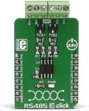
RS485 3 click uses SN65HVD31DR from Texas Instruments, a tri-state differential line driver and differential input line receiver. The click is intended to be used as UART to RS422/RS485 communication interface. It is suited for transmitting smaller blocks of data over long distances, using the four-wire bus, allowing for full-duplex communication.
It can be used as a transceiver between UART interface and RS422/RS485 communication bus. RS485 3 click can be used for controlling various building automation systems, light controllers, sensors and many small embedded devices that can all share the same bus, which can stretch up to 254 nodes and up to 1200m in length. |
|
|
|
 |
|
|
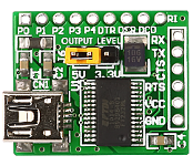
The USB UART Board features a USB to serial UART interface FT232R that simplifies USB to serial designs and reduces external component count by fully integrating an external EEPROM, USB termination resistors and a clock circuit requiring no external crystal, into the device. |
|
|
|
 |

|
|
For Alphanumeric LCD / Samsung KS0108 type GLCD.
If you need more pins, GLCD or character LCD for your applications than the Serial LCD/GLCD Adapter Board is the best choice. It is connected to an LCD/GLCD via the on-board MCP23S17 serial port expander that uses SPI communication. |
|
|
|
 |
|
|
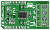
DC MOTOR 2 click carries the TB6593FNG driver IC for direct current motors. With two pairs of screw terminals (power supply and outputs), the click board can drive motors with voltages from 2.5 to 13V (output current of up to 1.2 amps with peaks up to 3.2 amps). The PWM signal drives the motor while the IN1 and IN2 pins provide binary direction signals that set the direction of the motor (clockwise or counter clockwise), or apply stop or short brake functions. Stop mode cuts off the power supply so the motor continues spinning until it runs out of momentum. Short break brings it to an abrupt stop. |
|
|
|
 |
|
|
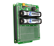
Battery Boost shield is an extension board pin-compatible with all mikroMMB boards from mikroElektronika that enables autonomous power supply using 2 x AAA batteries. Board features a compact monolithic integrated circuit MCP1640 that provides +4.0V power supply voltage.
|
|
|
|
 |

|
|
MOTION click is a motion detector sensitive only to live bodies. It carries PIR500B, a pyroelectric sensor which generates a voltage when exposed to infrared light. The signal is processed by a BIS0001 PIR sensor controller which sends an interrupt to the MCU through the mikroBUS INT (out) line. An onboard potentiometer lets you adjust the detecting range of the sensor (up to 4 meters). MOTION click also has a night only mode—resoldering a zero-ohm jumper activates the onboard photo resistor which acts as a light-sensitive switch. You can also switch the sensor ON and OFF by sending a signal from the MCU through the mikroBUS RST pin. The board uses a 3.3V power supply only. |
|
|
|
 |
|
|
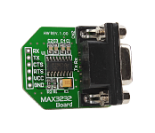
The Max3232 Board is used for establishing RS232 communication between a computer and devices powered by a power supply between 3.0V and 5.5V. The board features a MAX3232 (RS-232 transceiver) and female DB9 connector. |
|
|
|
 |

|
|
Touchkey click has four capacitive pads powered by TTP224, a touchpad detector IC. Capacitive buttons like these can be toggled even when placed under a layer of glass or paper.
|
|
|
|
 |

|
|
For Alphanumeric LCD.
The LCD Adapter Board is an effective and low-cost board used to connect your development board or prototype device to an LCD. There is an IDC10 connector as well as a potentiometer for LCD contrast adjustment provided on the board. |
|
|
|
 |
|
|
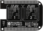
BeagleBone click shield is an extension for Beaglebone black, the popular low-cost development platform running Linux. This simple click shield (or cape if you prefer) has two mikroBUS sockets that allow you to connect more than 90 different types of click boards to BeagleBone black. It also has an EEPROM chip for storing pin configuration data. Quickly add functionalities like GSM, GPS, WiFi, ZigBee, Bluetooth, or thunder detection, proximity and color sensing and so on. The package includes two 2x12 headers and single 1x6 headers. |
|
|
|
 |
|
|
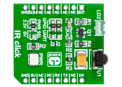
IR Click is an add-on board in the mikroBUS form factor. It is a compact and easy solution for adding an infrared (IR) remote control module to your design. It features the TSOP38338 IR receiver module as well as a QEE113 IR emitting diode. The 38 kHz receiver carrier frequency is recommended for RCMM, NEC, RC5, RC6, r-step and XMP codes. IR Click communicates with the target microcontroller via mikroBUS UART (Tx and Rx) or AN and PWM lines. Jumpers J2 and J3 allow you to choose between the two options. An SMD jumper is used to select between 3.3V or 5V power supply (soldered in 3.3V position by default). |
|
|
|
 |
|
|
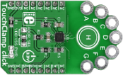
TouchClamp click is a mikroBUS add-on board with NXP's MPR121 proximity capacitive touch sensor controller. It has seven plated holes for clamps which can be used to connect any - literally any - conductive object in order to use it as an input button to send an interrupt to the target board MCU. It's great for creating installations where users interact with the environment in unexpected ways. There's also an extra capacitive button in the middle. TouchClamp click communicates with the target MCU through the mikroBUS INT pin and I2C interface (SCL, SDA). The board has an onboard ADDR. SEL. jumper for choosing I2C addresses. Designed to use a 3.3V power supply only. |
|
|
|
 |
|
|
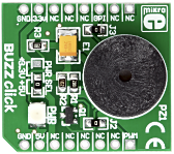
The Buzz Click board is an accessory board in mikroBus form factor. The board features a piezo speaker capable of emitting audio signals, with a resonant frequency of 3.8kHz. The on-board buzzer driver is connected to both the CS and PWM mikroBus lines. It is set to use the 5V mikroBus power supply by default, however soldering the PWR SEL SMD jumper to the 3.3V position will allow it to be used with 3.3V mikroBus systems. |
|
|
|
 |
|
|
 |
|
|
 |
|
|
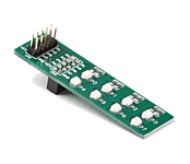
The EasyLED Board is an effective and low-cost solution for visual indication of output signals. LEDs are used for visual indication purposes. This board can be connected to a prototype device via an IDC10 connector.
|
|
|
|
 |
|
|
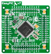
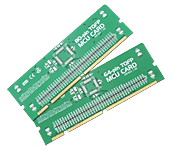
Supports the PIC18F8527-PT, PIC18F8622-PT, PIC18F8627-PT, PIC18F8722-PT, PIC18F8390-PT, PIC18F8490-PT, PIC18F8520-PT, PIC18F8620-PT, PIC18F8720-PT, PIC18F8310-PT, PIC18F8410-PT, PIC18F8585-PT and PIC18F8680-PT microcontrollers.
Can be used "standalone" (without a development system) for prototyping a design using one of the above microcontrollers. Comes with a 16MHz oscillator, as well as capacitors. |
|
|
|
 |
|
|
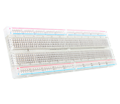
Standard solderless breadboard. It has 2 power buses, 62 columns and 10 rows - a total of 830 contact points. High-quality transparent plastic gives it a nice look. It contains self-adhesive tape at the bottom, which makes it convenient to stick to your PCB or other surface. The boards can interlock, so you can hook as many together as you like. Contact points are in standard 10 mill (2.54mm) pitch. |
|
|
|
 |
|
|
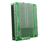
Mikromedia PROTO shield is an extension board pin-compatible with all mikromedia boards from mikroElektronika that enables users to place components and provide additional functionality to the base mikromedia board.
|
|
|
|
 |
|
|
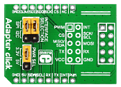
Adapter Click is a breakout board which simplifies the connection of add-on boards with mikroElektronika standard IDC10 headers to mikroBUS sockets. Connection can be made using either male or female IDC10 connectors. Both are provided with the package. You may solder a male IDC10 header on the top side of Adapter Click and connect the add-on board directly or via IDC10 flat cable. In some cases, a female header socket is a better choice. Solder it either on the top, or the bottom side, depending on which one is more convenient in the given circumstances. Each mikroBUS line is covered, except AN and RST. There are two jumpers for SPI/I2C selection and one for selection of power supply range. |
|
|
|
 |
|
|
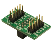
The EasyTEST Board is an ideal solution for connecting your prototype or development board to oscilloscope or other monitoring devices. This board can be connected to your development system or prototype device via an IDC10 connector. |
|
|
|
 |
|
|
 |
|
|
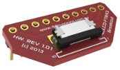
Breakout board for the 4DLCD-FT843 display. |
|
|
|
 |
|
|
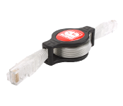
1 meter long ethernet cable, with roll mechanism. It features two RJ45 connectors and a flat cable. |
|
|
|
 |
|
|
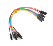
15cm long, 10 pieces.
Tip: Female to Female jumpers can be converted into either of the other two types, by simply inserting pins into their ends. |
|
|
|
 |
|
|
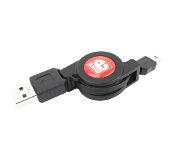
1 meter long USB type A to type Mini-B cable, with roll mechanism. It can be used to ease connections to your development tools and boards. |
|
|
|
 |
|
|
 |

