 |
|
|
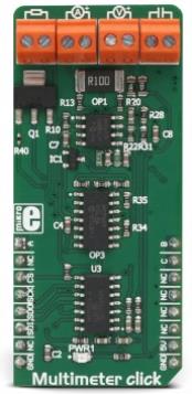
Multimeter click is a Click board™ designed to measure voltage, current, resistance, and capacitance properties of the components, connected to the input terminals. Each property measurement is done on a separate terminal. Each measurement section conditions the input signal from the respective input terminal and forwards it to a four-channel 12-bit A/D converter. All the inputs are equipped with the differential amplifiers, that allow both positive and negative signals to be measured. By utilizing the binary-to-decimal converter IC, it is possible to select the optimal range for the resistance measurement. Low internal resistance of only 0.1? for the current and high resistance of 1M? for the voltage measurement section, ensure no interferences with the measured circuitry, caused by this Click board™. |
|
|
|
 |
|
|
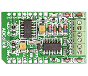
ADC Click is an accessory board in mikroBus form factor. It includes a 12-bit Analog-to-Digital Converter (ADC) MCP3204 that features 50k samples/second, 4 input channels and low-power consumption (500nA typical standby, 2uA max). Board uses industry standard SPI communication interface. It is small in size and features convenient screw terminals for easier connections. Board is set to use 3.3V power supply by default. Place PWR SEL SMD jumper to 5V position if used with 5V systems. |
|
|
|
 |
|
|
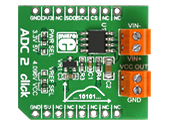
ADC 2 click carries MCP3551/3, which is a 22-bit ADC with automatic internal offset and gain calibration. This high precision analog-to-digital converter has total unadjusted error of less than 10 ppm, and low-output noise of 2.5 µV RMS. The board carries two pairs of screw screw terminals: VIN- for bringing in reference voltage, VIN+ for the positive voltage. VCC out and GND are output voltages. The click communicates with the target board through mikroBUS CS, CSK and MISO lines. Can use either a 3.3V or 5V power supply. |
|
|
|
 |
|
|
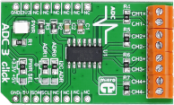
ADC3 click carries Microchip's MCP3428 16-bit multichannel analog-to-digital converter. The click has four pairs of screw terminals onboard, letting you access the chip's four differential input channels. At the highest resolution of 16-bits, the chip outputs conversion results at 15 samples per second. At 14-bits, the sample rate is 60 SPS. Maximum conversion speed is achieved in 12-bit mode, 240 samples per second. A pair of onboard jumpers allow switching between different I2C addresses. ADC3 click communicates with the target MCU through mikroBUS I2C pins (SCL, SDA). It is designed to use either a 3.3V or 5V power supply. |
|
|
|
 |
|
|
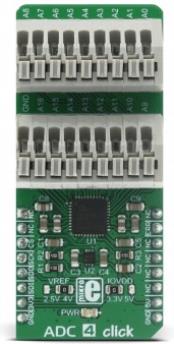
ADC 4 click is an advanced analog to digital multichannel converter, which can sample inputs from 16 single-ended channels or 8 differential input channel pairs. This device has a quite high sampling resolution of 24 bits and the output data rates can range from 5 SPS to 250 kSPS. Besides the internal 2.5V reference voltage source, ADC 4 click is also equipped with an external reference voltage circuit, which provides 4.096V. Finally, a custom reference voltage - up to 5V can be connected to the multiplexed inputs of the ADC converter. These options give a lot of flexibility in choosing the right reference voltage for any application.
Along with the two 9 pole spring action terminals that provide easy and secure connection to the input channels, this device has many other outstanding features, which make it a perfect choice for an accurate and simple digitalisation of analog signals from various sensors in PLC/DCS modules, temperature and pressure measurement, medical and scientific instrumentation, chromatography and other similar applications, where accurate analog to digital conversion is needed. |
|
|
|
 |
|
|
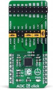
ADC 6 click is an advanced 24bit multichannel analog to digital converter (ADC), with 8 fully differential or 15 single ended/pseudo differential sampling inputs, and very flexible routing capabilities. The click board™ has two 2x10 pin headers, used both to configure the device and connect the input channels. This allows for unrestrained configuration of the device, so it can use both bipolar and unipolar input sources, with selectable reference voltages, external clock, auxiliary power switch, and more. |
|
|
|
 |
|
|
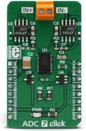
ADC 7 click is an advanced 32-bit analog to digital converter (ADC) which uses the LTC2500-32, a 32-bit oversampling SAR ADC with a configurable digital filter. The filter provides several presets (selectable via the hardware pin), as well as programming of the filtering parameters, via the industry-standard SPI interface. The LTC2500-32 has some very good specifications: a very low noise on the output, a high dynamic range of 148dB at 61 SPS (samples per second), 32-bit output with no missing codes, and more. An integrated filter allows relaxed anti-aliasing filter requirements for the analog input signal, which simplifies the design. |
|
|
|
 |
|
|
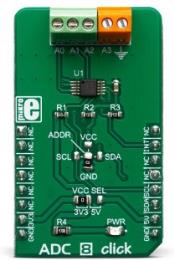
ADC 8 Click is a high precision, low-power, 16-bit analog-to-digital converter (ADC), based around the ADS1115 IC. It is capable of sampling signals on four single-ended or two differential input channels. Although the ADS1115 cannot use an external reference, it incorporates a low-drift programmable voltage reference, along with the programmable gain amplifier (PGA). This allows for great flexibility in terms of the input signal level: it can sample signals from ±256 mV, up to 6.144 V, allowing a very high precision for a wide range of input signals, making it an excellent choice for various instrumentation applications.
ADC 8 Click is supported by a mikroSDK compliant library, which includes functions that simplify software development. This Click board™ comes as a fully tested product, ready to be used on a system equipped with the mikroBUS™ socket.
|
|
|
|
 |

|
|
ADC 12 Click is a compact add-on board that contains a fully-featured, general-purpose analog-to-digital converter. This board features the ADS7828, a low-power 12-bit data acquisition device that features a serial I2C interface and an 8-channel multiplexer from Texas Instruments. The A/D converter features a sample-and-hold amplifier and an internal, asynchronous clock. The combination of an I2C serial interface, up to eight differential analog inputs, built-in reference with buffered output, and micro-power consumption makes this Click board™ ideal for applications requiring the A/D converter to be close to the input source in remote locations and for applications requiring isolation.
ADC 12 Click is supported by a mikroSDK compliant library, which includes functions that simplify software development. This Click board™ comes as a fully tested product, ready to be used on a system equipped with the mikroBUS™ socket.
|
|
|
|
 |
|
|
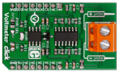
Voltmeter click is a mikroBUS add-on board for measuring voltage in an external electric circuit.
The board is designed to measure Direct Current only, and has a measurement range from 0 to 24V (it's possible to measure both positive and negative charges).
The design of the board is based on an OpAmp set up as a differential amplifier with a buffered input.
Two onboard screw terminals (probe+ and probe-) are bringing in the current, which then flows through a row of four resistors. A voltage – proportional to the input charge – is generated across the last two resistors. From there it is sent to the differential amplifier that further intensifies the difference between the two inputs (+/-).
The resulting charge is exactly 33 times lower than the actual measured voltage. It is converted by an onboard 12-bit ADC before being outputted through the mikroBUS SPI interface (the firmware in the target board MCU should be set up to multiply the ADC value to get the actual voltage). It is also possible to output the analog value directly through the mikroBUS AN pin (useful if the target MCU has a higher resolution ADC).
The board can work with either a 3.3V or a 5V power supply. |
|
|
|
 |
|
|
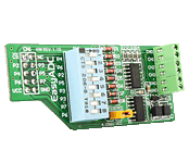
The EasyADC Board enables you to connect your development board to a 12-bit analog-to-digital converter (ADC). The board features a 12-bit analog-to-digital converter (ADC) MCP3204 with 4 inputs and 4.096 voltage reference. |
|
|
|
 |
|
|
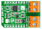
Current Click is an add-on board used for the measurement of electric current. It features an INA196 current shunt monitor, MCP3201 12-bit ADC, MAX6106 voltage reference as well as two screw terminals. The board receives current from the output circuit connected to IN(+) and OUT(-) pins of the first screw terminal connectors. INA196 IC converts this current into a voltage. The second screw terminal is used for external shunt. In order to measure current values in various bands, you need to provide the shunt of the appropriate value. Four shunts with different values are provided in the package. Current Click communicates with the target microcontroller via mikroBUS SPI or AN lines. The board is designed to work with either a 3.3V or 5V power supply. |
|
|
|
 |
|
|
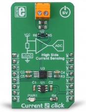
Current 2 click is an accurate current sensing Click board™ suitable for a very accurate measurement of the current through the load. It utilizes the high-side current sensing approach, which has a few advantages over the low-side current sensing. Current 2 click is equipped with an integrated transimpedance amplifying circuit, designed specifically for low-power current sensing applications. Designed to be used with a common mode voltage up to 6V, this Click board™ is a perfect solution for the battery charging monitoring, various battery gauges, and other similar low voltage applications that require simple and reliable current monitoring.
It comes in the package which also includes the mikroSDK™ software and a library with all the functions. The Click board™ comes as a fully tested and approved prototype, making it a reliable device ready to use on the development board.
|
|
|
|
 |
|
|
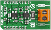
Ammeter click is a mikroBUS add-on board with circuitry for measuring electric current (both AC and DC).
Two onboard screw terminals (probe+ and probe-) are bringing in the current, which then passes through a shunt resistor. A voltage proportional to the strength of the current is generated accross the resistor. This voltage passes through an amplifier before it's fed into a 12-bit ADC which then outputs a digital value through the mikroBUS SPI interface.
The firmware processes the digital value to determine the exact amperage between 1mA and 1A for DC current. It's also possible to measure AC current by deriving the value from peak to peak measurements. At the same time, the voltage can be directly monitored through the AN pin.
The board uses either a 3.3V or 5V power supply (it's important not to power the board from the same power source you wish to measure). |
|
|
|
 |

|
|
Hall current click is a high precision current sensor. It carries a galvanically isolated TLI4970-D050T4 miniature magnetic digital current sensor that utilizes the Hall effect to measure electric current. It can detect current levels from -49 to +49 amps, both AC and DC. The board carries two EXTreme ZPower connectors (IP- and IP+) to connect the conductor. The current rail is galvanically isolated from the interface to the microcontroller. The sensor readings are sent to the target board through the mikroBUS SPI (SDO, SCK, and CS) lines. The board uses a 3.3V power supply only.
Hall current click can be used with dangerous voltage levels. Use caution when working with current and the Hall current click - DO NOT TOUCH THE BOARD WHILE THE EXTERNAL POWER SUPPLY IS ON! |
|
|
|
 |
|
|
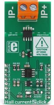
Hall current 2 click is a very accurate current measurement Click board™, which relies on the Hall effect. Its most distinctive feature is a very low series resistance of only 1.2m?, making this device a nearly-perfect ampere meter. The maximum current which can be measured with the Hall current 2 ranges from -12A to +12A, with optimized precision. The measurement is thermally compensated and conditioned by the integrated sections of the hall sensor IC. The result is available via the I2C interface of the high precision, 12 bit AD converter, as well as in the analog form, from the analog pin of the microBUS™, directly from the Hall effect current sensor IC. This click board does not require any current sensing resistors. |
|
|
|
 |
|
|
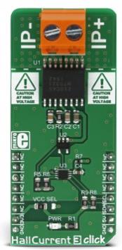
Hall current 3 click is a very accurate current measurement Click board™, which utilizes the Hall effect to provide a precise and reliable measurement of reasonably high current. Its most distinctive feature is a very low series resistance of only 0.7m?, making this device a nearly-perfect ammeter. The maximum current which can be measured by the MLX91210 integrated Hall sensor IC goes up to ±30A, but in respect to the nominal current measurement rating of the sensor, the current measurement is limited to about ±10A. The measurement is thermally compensated and conditioned by the high-speed integrated analog front-end sections of the Hall sensor IC. The current measurement value can be obtained from the onboard 12bit A/D converter, via the I2C interface. |
|
|
|
 |
|
|
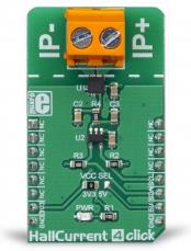
The Hall Current 4 click is designed to measure relatively high current by using the integrated ACS70331 sensor. The current sensor is based on the GMR elements for current measurement. The Hall Current 4 can be used for current measurement in the applications designed to follow a current, such as the applications for monitoring the current in battery chargers, or for the various kinds of system power supplies.
It comes in the package which also includes the mikroSDK™ software and a library with all the functions. The Click board™ comes as a fully tested and approved prototype, making it a reliable device ready to use on the development board.
|
|
|
|
 |
|
|
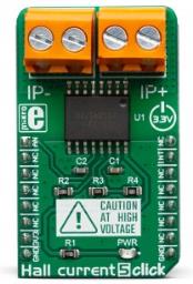
Hall Current 5 Click is a very accurate electric current measurement Click board™ based on the ACS733 IC. This IC is a galvanically isolated current sensor, which utilizes the Hall-effect principle. Its most distinctive feature is its very low series resistance of only 1 m?, which makes this device a nearly-perfect ammeter. The maximum current which can be measured with Hall current 5 click ranges from -20 A to +20 A, with the optimized precision. By using the latest manufacturing technologies, the ACS733 can be used on very high frequencies, making it a perfect solution for a wide range of applications.
Hall current 5 Click is supported by a mikroSDK compliant library, which includes functions that simplify software development. This Click board™ comes as a fully tested product, ready to be used on a system equipped with the mikroBUS™ socket.
|
|
|
|
 |
|
|
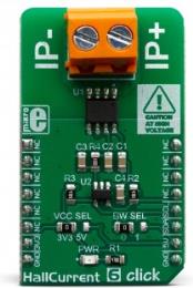
Hall Current 6 Click is a very accurate current measurement Click board™, based on the ACS723 IC. This IC is a galvanically isolated current sensor, which utilizes the Hall-effect principle. Its most distinctive feature is its very low series resistance of only 0.65 m?, which makes this device a nearly-perfect ammeter. The maximum current which can be measured with Hall Current 6 click ranges from -5 A to +5 A, with the optimized precision. It features a dedicated bandwidth selection pin, which allows better noise performance for a specific application.
Hall Current 6 Click is supported by a mikroSDK compliant library, which includes functions that simplify software development. This Click board™ comes as a fully tested product, ready to be used on a system equipped with the mikroBUS™ socket.
|
|
|
|
 |

|
|
AC Current click can measure alternating currents up to 30A. The board features the MCP3201 ADC (analog to digital converter) and the MCP607 CMOS Op Amp, both from Microchip. The click is designed to run on either a 3.3V or 5V power supply. It communicates with the target MCU over an SPI interface, and the AN pin on the mikroBUS™ line. |
|
|
|
 |

|
|
The LDC1000 click board carries the world's first inductance-to-digital converter IC, along with a detachable sensor (an LC tank comprising a 36-turn PCB coil and a 100pF 1% NPO capacitor). The LDC1000 IC has a sub-micron resolution in short range applications; the board is ideal for highly precise short range measurements of the position, motion or composition of conductive targets. Inductive sensing is highly reliable: harsh conditions don't hinder the performance of LDC1000 IC. Onboard INA and INB pins allow you to replace the provided detachable sensor and solder your own. LDC1000 click communicates with the target board through mikroBUS SPI (CS, SCK, MISO, MOSI) and INT lines. The board is designed to use either a 3.3V or a 5V power supply. |
|
|
|
 |
|
|
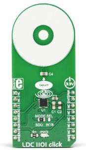
LDC1101 click is an inductance-to-digital converter Click Board™. It is designed for a range of different applications, based on the inductivity measurements. You can use it to detect the position, rotation, or motion of an object. LDC1101 carries the LDC1101, the integrated, high-resolution, high-speed, inductance-to-digital converter. The converter allows both the inductance and the impedance to be measured. The fast impedance + inductance (RP+L) mode offers separate 16-bit readings for both parameters, while the high-resolution inductance (LHR) mode offers a single reading with a resolution of 24 bits.
It comes in the package which also includes the mikroSDK™ software and a library with all the functions. The Click board™ comes as a fully tested and approved prototype, making it a reliable device ready to use on the development board.
|
|
|
|
 |
|
|
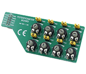
The Potentiometer Board is an accessory board offering an effective, low-cost solution for testing analog inputs on a prototype board. Connect your prototype device to the Potentiometer Board using an IDC10 connector. |
|
|
|
 |
|
|
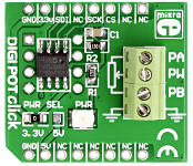
DIGIPOT Click is an accessory board in mikroBus form factor. It features a single-channel digital potentiometer MCP4161 with 8-bit resolution (256 wiper steps) and industry-standard SPI serial interface. The resistance value of the digital potentiometer goes up to 10k. It features outstanding AC/DC characteristics and low power consumption. It can be used in audio equipment, servo-motor control, battery charging and control, LCD contrast control, programmable filters etc. |
|
|
|
 |
|
|
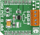
DIGI POT 2 click is a mikroBUS add-on board with a single channel digital potentiometer TPL0501 with 256 wiper positions. The IC has 100 kilo Ohms end-to-end resistance, with ± 20% tolerance. The board features two pairs of screw terminals for interfacing with the IC DIGI POT 2 click communicates with the target MCU through the mikroBUS SPI pins (MISO, MOSI, SCK, CS). The board is designed to use either a 3.3 or a 5V power supply. |
|
|
|
 |
|
|
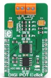
DIGI POT 3 click is a versatile and feature-rich digital potentiometer click with 1024 steps and an internal non-volatile memory (EEMEM), which can be used for storing the wiper position, but also for storing various user data. The user EEMEM area has 14 words, each with 16bit length. The Click board™ can be used with both unipolar and bipolar signals, selectable by onboard SMD jumpers. The wiper position can be increased or decreased linearly or by the logarithmic scale (6db/step) with a single command. A special scratch register allows direct programming of the wiper position. It can be stored to the non-volatile memory and on the power on, it is automatically restored. This means that the device restores its last position after the power on - just like its mechanical counterpart. |
|
|
|
 |
|
|
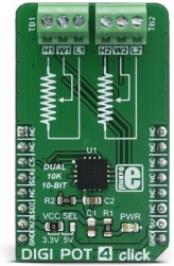
DIGI POT 4 click is a digitally controlled dual potentiometer, with the resistance of 10K?. It has a 10bit resolution which allows for a very smooth linear wiper positioning through 1024 steps. Digital wiper position can be controlled via SPI interface. DIGI POT 4 click also features a non-volatile durable EEPROM memory for storing the wiper position, which means that the device can restore its last position after the power on - just like its mechanical counterpart.
The main advantage of the digital potentiometers over the mechanical ones is that they can never wear out. The wiper position can be precisely programmed, and the wiper contact with the resistive coating can never be compromised by the influence of the dirt or moisture. Due to its low THD and good bandwidth, it can be used for digital volume control or a precise gain and offset adjustment. It can also be used as the LCD digital contrast control, and generally - whenever a precise dual digital voltage divider application is required.
|
|
|
|
 |
|
|
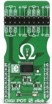
DIGI POT 5 click is a digitally controlled quad potentiometer, with the resistance of 10K?. It has an 8bit wiper step resolution, which allows the wiper to take 257 different discrete positions (across 256 internal resistors). The digital wiper position can be controlled via the SPI interface. DIGI POT 5 click features a durable EEPROM non-volatile (NV) memory for storing the wiper position. The content of the wiper register memory located in the NV memory is copied to the actual wiper registers after the power-on or reset state, so the device acts similar to its mechanical counterpart, recalling its last used wiper position after being powered on. The device also features the WiperLock™ technology, which effectively locks the wiper position in place.
DIGI POT 5 click has a multitude of practical uses in electronic circuits. The most popular uses include precision calibration of set point thresholds, sensor trimming, LCD contrast adjustment, audio attenuation, an adjustable gain for amplifiers and offset trimming. DIGI POT 5 click can be used to replace the common mechanical trim pot, in a wide range of different applications where the operating voltage stays within the limits. |
|
|
|
 |
|
|
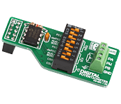
The Digital Potentiometer Board includes a SPI Interfaced single-channel digital potentiometer MCP41010. The board enables you to set potentiometer values from 0 to 10k. It comes with many simple and ready-to-use examples. |
|
|
|
 |
|
|
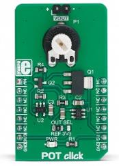
POT Click is a Click board™ with the accurate selectable reference voltage output. By employing a high-quality 10mm carbon potentiometer, this Click board™ can provide very accurate voltage output. POT 2 click is also equipped with the SMD jumper, which allows the maximum reference voltage to be selected between two typically used values: 2.048V or 3.3V. The output is buffered with a rail-to-rail buffering operational amplifier, provides constant input and output impedance. The output current is limited by the protection circuit at the output, preventing damage if the output is shorted to GND.
POT click is supported by a mikroSDK compliant library, which includes functions that simplify software development. This Click board™ comes as a fully tested product, ready to be used on a system equipped with the mikroBUS™ socket.
|
|
|
|
 |
|
|
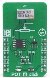
POT 2 click is a Click board™ with the accurate selectable reference voltage output. By utilizing a multi-turn precision potentiometer, this Click board™ can provide very accurate voltage output on the AN pin of the mikroBUS™. POT 2 click is also equipped with the SMD jumper, which allows the maximum reference voltage to be selected between two typically used values: 2.048V or 4.096V. Using a rail-to-rail buffering operational amplifier which provides constant input and output impedance, this Click board™ is an ideal solution when accurately controlled voltage reference is required.
POT 2 click is supported by a mikroSDK compliant library, which includes functions that simplify software development. This Click board™ comes as a fully tested product, ready to be used on a system equipped with the mikroBUS™ socket.
|
|
|
|
 |
|
|
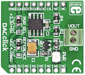
The DAC Click board is an accessory board in mikroBus form factor. It includes the MCP4921 12-bit Digital-to-Analog Converter which features a SPI interface and optional dual-buffered output. The board provides high accuracy and low noise performance for industrial applications where calibration or compensation of signals, such as temperature, pressure and humidity, are required. The board is set to use the 3.3V mikroBus power supply by default, however soldering the PWR SEL SMD jumper to the 5V position will allow it to be used with 5V mikroBus systems. |
|
|
|
 |
|
|
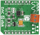
DAC2 click carries LTC2601CDD, a 16-bit digital-to-analog converter, along with voltage output screw terminals. The chip has high rail-to-rail output drives (±15mA, Min) and double-buffered data latches. The click board communicates with the target MCU through the mikroBUS SPI interface with clock rates up to 50MHz. Additionally, the CLR pin, in place of default mikroBUS RST pin, clears all the registers. The board uses either a 3.3V or 5V power supply. You can also set the reference voltage either to VCC or 4.096V. |
|
|
|
 |
|
|
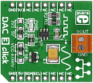
DAC3 click carries Microchip's MCP4726 IC, a 12-bit digital-to-analog converter, along with voltage output screw terminals. The digital value is converted to the appropriate voltage level in the range between GND and REFERENCE (VCC or 4.096V), which is proportional to the received 12-bit number. MCP4726 also integrates EEPROM for storing DAC register and configuration bit values. The board communicates with the target board MCU through the mikroBUS I2C interface (SCL, SDA pins). Standard (100 kHz), fast (400 kHz) and highspeed (3.4 MHz) I2C modes are available. Uses either a 3.3V or a 5V power supply. |
|
|
|
 |
|
|
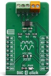
DAC 4 Click carries Microchip's MCP4728 IC, a Quad Digital-to-Analog Converter with nonvolatile (EEPROM) Memory. The digital value is converted to the appropriate voltage level in the range between GND and VCC, which is proportional to the received 12-bit number. MCP4726 also integrates EEPROM for storing DAC register and configuration bit values. These options give a lot of flexibility which make it a perfect choice for an accurate and simple generation of analog signals for various purposes, such as PLC/DCS modules, temperature and pressure control, medical and scientific instrumentation, chromatography and other similar applications, where accurate digital to analog conversion is needed.
DAC 4 click board™ is supported by a mikroSDK compliant library, which includes functions that simplify software development. This Click board™ comes as a fully tested product, ready to be used on a system equipped with the mikroBUS™ socket.
|
|
|
|
 |
|
|
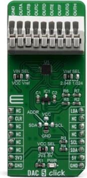
DAC 5 Click carries Texas Instruments DAC53608 IC, a low-power, eight-channel, 10-bit buffered Digital-to-Analog Converter. DAC53608 converts digital value to the corresponding voltage level using external voltage reference. For that purpose, DAC 5 click uses MAX6106, which is a low-dropout micropower voltage reference with 2,048V output voltage. With all those possibilities on board, DAC 5 click makes a perfect choice for an accurate and simple generation of analog signals for various purposes, such as programmable Power Supplies, Laser Drivers, Projectors, IP Network cameras, auto focus digital still camera lens, and more.
DAC 5 click board™ is supported by a mikroSDK compliant library, which includes functions that simplify software development. This Click board™ comes as a fully tested product, ready to be used on a system equipped with the mikroBUS™ socket.
|
|
|
|
 |
|
|
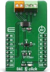
DAC 7 click carries the AD5624R, a low-power four-channel, 12-bit buffered Digital-to-Analog Converter from Texas Instruments. AD5624R converts digital value to the corresponding voltage level using external voltage reference. This will help you convert digital information from the main board to four analog outputs on the DAC 7 click. For that purpose, DAC 7 click uses MCP1541, which is a low-dropout precision voltage reference with 4.096V output voltage. With all those possibilities on board, DAC 7 click makes a perfect choice for an accurate and simple generation of analog signals for various purposes, such as programmable Power Supplies, Laser Drivers, Projectors, IP Network cameras, auto focus digital still camera lens, and more.
DAC 7 click board™ is supported by a mikroSDK compliant library, which includes functions that simplify software development. This Click board™ comes as a fully tested product, ready to be used on a system equipped with the mikroBUS™ socket.
|
|
|
|
 |
|
|
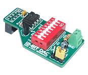
The DAC Board is an accessory board provided with a D/A converter MCP4921 with a serial peripheral interface (SPI). This board is ideal for connecting microcontrollers with analog devices. |
|
|
|
 |
|
|
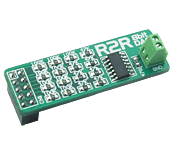
The R2R DAC Board features an on-board digital-to-analog converter R2R that uses R/2R-network and rail-to-rail operational amplifier MCP6284 (450 uA, 5 MHz). The board is connected to a prototype device via an on-board IDC10 connector |
|
|
|
 |

|
|
Comparator click, carrying the LM2903 IC, which has two independent precision voltage comparators. Two pairs of screw terminals allow you to connect separate inputs (additional two screw terminals are for GND connections). You can use it either with a single (range of 2.0 VDC to 36 VDC) or dual power supply (from ± 1.0 VDC to ±18 VDC). Two potentiometers are placed between the terminals and the IC. Each input has its own Interrupt pin on the mikroBUS socket (one on the INT pin, the other in place of the mikroBUS AN pin), marked 01 and 02. |
|
|
|
 |
|
|
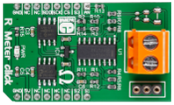
R Meter click is a mikroBUS add-on board with circuitry for measuring the value of resistors. The board can be used to measure a wide range of resistors (from 0 to 1 Mega Ohm) The design is based on a non-inverting amplifier circuit, with the measured resistor placed in a feedback loop that influences the gain of the amplifier.
The analog output is fed through a 12-bit ADC with the final output going through the mikroBUS SPI interface.
Since the ADC has a limited min-max range (0-2043), R Meter click employs a multiplexer that can adjust the input signal to the amplifier and thus allow the same ADC to measure four different scopes of values (0-1k , 1k-100k, 100k-1M)
The supplied firmware automatically scans the ADC value and switches the multiplexer output based on the resistor in place. The multiplexer interfaces directly with the target board MCU through mikroBUS S1, S2, and S3 pins (in place of default mikroBUS PWM, INT and RST).
Onboard screw terminals are placed to allow the click to be used with multimeter probes.
The board is designed to use a 5V power supply. |
|
|
|
 |
|
|
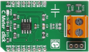
C Meter click is a mikroBUS add-on board with circuitry for measuring the value of capacitors. The design is based on a NE-555 timer/square-wave generator. The chip is implemented in an astable multivibrator circuit with fixed resistors and adjustable capacitors.
The board has four different-sized plates for placing SMD capacitors (covering standard SMD packaging dimensions) as well as a socket for inserting a thru hole capacitor.
The board outputs a square wave frequency through the INT pin. Depending on the capacitor placed on the board, the value of this frequency changes. The value of a capacitor can be inferred using a simple algorithm (shown in the Libstock code example).
Onboard screw terminals are placed to allow the click to be used with multimeter probes.
C Meter click is designed to use a 5V power supply, but can work with either 3.3V or 5V logic levels. |
|
|
|
 |
|
|
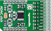
ADAC click is an 8-channel 12-bit ADC, DAC and GPIO.
The click is designed to run on either 3.3V or 5V power supply. ADAC click communicates with the target microcontroller over I2C interface, with additional functionality provided by the RST pin on the mikroBUS™ line. |
|
|
|
 |

|
|
ADAC 3 Click is a compact add-on board representing the ADC/DAC combo solution. This board features the PCF8591, a low-power 8-bit CMOS data acquisition device with four analog inputs, one analog output, and a serial I2C interface from NXP Semiconductors. The PCF8591 includes analog input multiplexing, an on-chip track and hold function and 8-bit analog-to-digital conversion alongside an 8-bit digital-to-analog conversion. In addition, the user is given the option to select the PCF8591 reference voltage value, choosing between 2,048 and 4,096V. This Click board™ is suitable for various control, monitoring, or measurement applications such as supply monitoring, reference setting, analog control loops, and more.
ADAC 3 Click is supported by a mikroSDK compliant library, which includes functions that simplify software development. This Click board™ comes as a fully tested product, ready to be used on a system equipped with the mikroBUS™ socket.
|
|
|
|
 |
|
|
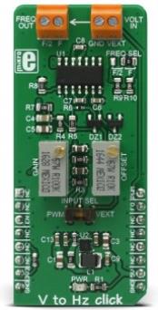
V to HZ click is a device that turns analog voltage into a pulse wave signal of a certain frequency. It has a linear response, so applying a voltage in a range of 0 to 5V on its input, will result in generating the pulse train with frequency linearly proportional to the input voltage. This click features very good linearity, covers a frequency range from 10Hz to 10 kHz and it has a good temperature stability.
These features allow this device to be used in various voltage to frequency applications: it can be used in various applications in instrumentation, industrial, and automation markets. It is well suited for use in AD conversion, long-term integration, linear frequency modulation, voltage-to-frequency conversion and it can be used as the variable clock signal generator. |
|
|
|
 |
|
|
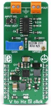
V to Hz 2 click is a device that converts an analog voltage input signal into a pulse wave signal of a certain frequency. It has a linear response, so applying a voltage in a range of 0 to 3.3V on its input, will result in generating the pulse train with frequency linearly proportional to the input voltage. This click features very good linearity, covers a frequency range between 200 Hz to 120 kHz, and it has good temperature stability. |
|
|
|
 |
|
|
Frequency-to-voltage converter with a linear response
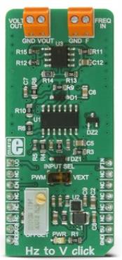
HZ to V click is a device that can convert input frequency of the signal with virtually any wave shape to a DC voltage output, with a level proportional to the input frequency. It has a linear response, and by applying a signal with the frequency between 10Hz to 10kHz on its input, the Click board™ will generate a DC voltage, ranging from 0V to 3.3V. Hz to V click features very good linearity, covers a wide input frequency range from 10Hz to 10kHz and it has good temperature stability. |
|
|
|
 |
|
|
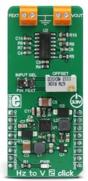
HZ to V 2 click is a device that can convert input frequency of the signal with virtually any wave shape to a DC voltage output, with a level proportional to the input frequency. It features a specialized IC labeled as VFC32KU, which has a good linear response and temperature stability. By applying a signal with the frequency up to 120kHz on its input, the Click board™ will generate a DC voltage up to 3.3V. The IC is supplied by a dual-voltage boost DC/DC converter IC, which provides the power supply of ±15V, required for the VFC32KU IC operation. |
|
|
|
 |
|
|
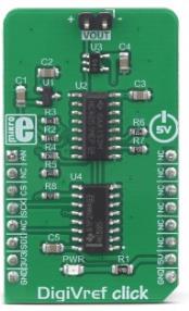
DigiVref click is a very precise voltage reference Click board™, which allows one of four different voltage values to be selected over the SPI interface. Once the selection is done, the voltage reference stays fixed, even when the SPI interface is completely disconnected. The voltage reference is buffered by an operational amplifier, and thus it is very stable. Thanks to the MCP1541, a high precision voltage reference IC, and high thermal stability used resistors, the output voltage remains highly regulated, keeping the thermal drift very low. It can be used whenever a precise voltage reference is required.
DigiVref click is supported by a mikroSDK compliant library, which includes functions that simplify software development. This Click board™ comes as a fully tested product, ready to be used on a system equipped with the mikroBUS™ socket.
|
|
|
|
 |
|
|
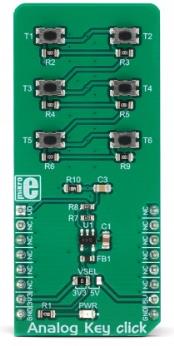
Analog Key Click is an analog keyboard on a Click board™. It contains six tactile pushbuttons, used to select one of six different voltage levels. The idea behind this click is very simple: six resistors form a voltage divider. The resistors are connected in series between the VCC and the GND. Each button selects one of the six middle taps, allowing six different voltage levels to be selected. The voltage is available at the AN pin of the mikroBUS™, which is additionally protected by an operational amplifier, configured as a buffer. This allows both protection and a proper impedance at the analog input pin of the microcontroller.
|
|
|
|
 |
|
|
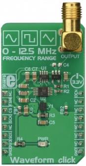
Waveform Click is a precise sine/triangle/square waveform generator, capable of reproducing frequencies up to 12MHz. It utilizes a Direct Digital Synthesis (DDS) IC made by Analog Devices, a company famed for its specialization in DSP development and engineering. The AD9833 waveform generator IC requires a very low count of additional components: besides the external clock source, it requires almost no components, allowing the Click board™ to be equipped with some additional circuits. A digital potentiometer IC is used to attenuate the output signal, while the high-quality op-amp is used as a buffer.
Waveform click is supported by a mikroSDK compliant library, which includes functions that simplify software development. This Click board™ comes as a fully tested product, ready to be used on a system equipped with the mikroBUS™ socket.
|
|
|
|
 |
|
|
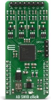
AD-SWIO Click is a quad-channel software configurable input/output solution based on AD74412R. The AD74412R is a quad-channel software configurable input/output integrated circuit for building and process control applications. The device provides a fully integrated single chip solution for input and output operation. The AD-SWIO Click contains four 13-bit DACs, one per chanal, and 16-bit S-? ADC. These options give a lot of flexibility in choosing functionality for analog output, analog input, digital input, resistance temperature detector (RTD), and thermocouple measurements integrated into a single chip solution with a serial peripheral interface (SPI).
The AD-SWIO Click is supported by a mikroSDK compliant library, which includes functions that simplify software development. This Click board™ comes as a fully tested product, ready to be used on a system equipped with the mikroBUS™ socket.
|
|
|
|
 |
|
|
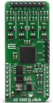
AD-SWIO 2 Click is a quad-channel software configurable input/output solution based on AD74413R, for building and process control application. The AD74413R is a quad-channel software configurable input/output solution for building and process control applications. The device provides a fully integrated single chip solution for input and output operation. The AD-SWIO 2 Click contains four 13-bit DACs, one per chanal, and 16-bit S-? ADC. These options give a lot of flexibility in choosing functionality for analog output, analog input, digital input, resistance temperature detector (RTD), and thermocouple measurements integrated into a single chip solution with a serial peripheral interface (SPI).
The AD-SWIO 2 Click is supported by a mikroSDK compliant library, which includes functions that simplify software development. This Click board™ comes as a fully tested product, ready to be used on a system equipped with the mikroBUS™ socket.
|
|
|
|
 |

|
|
ADC 10 Click is a compact add-on board that contains a high-performance data converter. This board features the ADS122U04, a 24-bit precision ?S analog-to-digital converter with UART compatible interface from Texas Instruments. It features two differential or four single-ended inputs through a flexible input multiplexer, a programmable gain amplifier up to 128, two programmable excitation current sources, a voltage reference, an oscillator, and a temperature sensor. The ADS122U04 offers conversions at data rates up to 2000 samples-per-second with single-cycle settling. This Click board™ is suitable for measuring small sensor signals, such as resistance temperature detectors (RTDs), thermocouples, thermistors, and resistive bridge sensors.
ADC 10 Click is supported by a mikroSDK compliant library, which includes functions that simplify software development. This Click board™ comes as a fully tested product, ready to be used on a system equipped with the mikroBUS™ socket.
|
|
|
|
 |

|
|
Analog MUX 2 Click is a compact add-on board that switches one of the eight inputs to one output. This board features the ADG728, a low voltage, CMOS 8-channel analog matrix switch with a serially controlled 2-wire interface from Analog Devices. The ADG728 can operate equally well as either multiplexer, demultiplexer, or switch array easily connected to a 9 pole spring action block terminal. It provides flexibility and features a low on-resistance closely matched between switches and very flat over the full signal range. This Click board™ is suitable for a wide range of applications, from industrial and instrumentation to medical, consumer, communications, and automotive systems.
Analog MUX 2 Click is supported by a mikroSDK compliant library, which includes functions that simplify software development. This Click board™ comes as a fully tested product, ready to be used on a system equipped with the mikroBUS™ socket.
|
|
|
|
 |

|
|
Analog MUX 3 Click is a compact add-on board that switches one of the eight inputs to one output. This board features the ADG738, a CMOS analog matrix switch with a serially-controlled SPI interface from Analog Devices. In an active state, the ADG738 conducts equally well in both directions, making it suitable for multiplexing and demultiplexing applications. It can also be configured as a type of switch array where any, all, or none of eight switches may be closed any time. All channels exhibit ‘break-before-make switching action, preventing momentary shorting when switching channels. This Click board™ is suitable for a wide range of applications, from industrial and instrumentation to medical, consumer, communications, and automotive systems.
Analog MUX 3 Click is supported by a mikroSDK compliant library, which includes functions that simplify software development. This Click board™ comes as a fully tested product, ready to be used on a system equipped with the mikroBUS™ socket.
|
|
|
|
 |
|

