The EMC1833 features a high accuracy of ±1°C within the range between -40°C and +125°C, which is a critical thermal bandwidth of most IC with the substrate PNP or NPN transistor as a temperature sensor. However, the Click board™ can be operated within the range between -40°C to +125°C when used to measure the Internal/External temperature. Features such as dual temperature measurement, high accuracy, and programmable ALARM events, allow this Click board™ to be used in many applications, including dual-zone thermal monitoring in FPGA, embedded, and PC systems, i.e. when it is required to monitor both the ambient temperature within the enclosure, as well as the IC die temperature, for test and measurement applications, and similar.
How does it work?
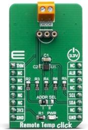
The main component of the Remote Temp click is the EMC1833, a ±1°C, SMBus/I2C compatible local/remote temperature sensor with an overtemperature alarm, produced by Microchip. This sensor is capable of measuring its own temperature, as well as the temperature of the remote BJT junction, which can be either a discrete PNP or NPN transistor, or a substrate of some integrated component (typically CPU, FPGA, ASIC or GPU).
- Substrate PNP transistors collector connected to the DP pin, a base connected to DN pin of EMC1833 and emitter is grounded.
- Discrete NPN transistor (2N3904) with its collector and base connected to DP pin, while the emitter is connected to the DN pin of the EMC1833.
- Anti-parallel connected discrete NPN transistors, collector and base of the first transistor connect to emitter of second transistor and DN2 pin of EMC1833, emitter of the first transistor connected to collector and base of second transistor and DP2 of pin EMC1833.

There are some specific requirements for a discrete component when using it as a remote temperature sensor: for example, it has to be a small signal BJT. For more information, please refer to datasheet of the EMC1833, which also states some forward voltage ranges for the highest and the lowest expected temperatures and other parameters which should be considered when selecting the transistor. The discrete component can be connected to the screw terminal at the edge of the Click board™.
The EMC1833 features a 11-bit ADC which results in having the 0.125°C resolution. The temperature measurement results are stored in the internal and external temperature registers. Both external and internal temperature measurements are stored in 11-bit format with the eight Most Significant bits (MSb) stored in a high-byte register and the three Least Significant bits (LSb) stored in the three MSB positions of the low-byte register. All other bits of the low-byte register are set to zero. The EMC1833 IC automatically sends biasing current through the BJT junctions, while the IC samples the forward voltage for the given current and calculates the temperature. The ADC integrates the result over a period of 21ms, reducing the noise that way. Therefore, the temperature acquisition is not particularly fast. In return, the temperature measurement results are more accurate and reliable.
The accuracy of the remote measurement depends on the ideality factor of the remote BJT junction. Not all external diodes, processor or discrete, will have this exact value. This variation of the ideality factor introduces errors in the temperature measurement which must be corrected for. Therefore, the EMC1833 features Programmable External Diode Ideality Factor, which can be easily set by changing the value in the appropriate register.
The EMC1833 IC also features the ALERT reporting capability. If a programmed threshold is exceeded, the ALERT pin will be asserted to a LOW logic level. When the ALERT pin is asserted, it will remain latched until its STATUS register is read after the overtemperature condition no longer exists. Another way to clear the ALERT interrupt is to respond to the alert response address. This is a global I2C/SMBus protocol, where the host MCU broadcasts a Receive Byte transmission after the interrupt is received. One (or more) slave devices which generated this interrupt will respond, sending their I2C slave address, following the bus arbitration rules. This protocol is explained in more details within the EMC1833 datasheet. The ALERT pin is routed to the INT pin of the mikroBUS™ and it is pulled up by a resistor.
The slave address decode is performed by pulling known currents from the VDD pin through the external resistor, causing the pin voltage to drop based on the respective current/resistor relationship. This pin voltage is compared against a threshold that determines the value of the pull-up resistor.
This Click Board™ is designed to be operated only with 3.3V logic level. A proper logic voltage level conversion should be performed before the Click board™ is used with MCUs with logic levels of 5V. It is ready to be used as soon as it is inserted into a mikroBUS™ socket of the development system.
Specifications
| Type |
Temperature & humidity |
| Applications |
It can be used in many applications, including dual-zone thermal monitoring in FPGA, embedded, and PC systems, i.e. when it is required to monitor both the ambient temperature within the enclosure. |
| On-board modules |
EMC1833, a ±1°C, SMBus/I2C compatible local/remote temperature sensor with an overtemperature alarm, produced by Microchip. |
| Key Features |
A very high measurement accuracy and repeatability, ALARM thresholds, a dedicated ALARM interrupt pin, dual zone thermal monitoring (ambient temperature and remote temperature), suitable to be used for the on-chip BJT junctions, etc. |
| Interface |
I2C |
| Click board size |
M (42.9 x 25.4 mm) |
| Input Voltage |
3.3V |
Pinout diagram
This table shows how the pinout on Remote Temp click corresponds to the pinout on the mikroBUS™ socket (the latter shown in the two middle columns).
| Notes |
Pin |
 |
Pin |
Notes |
|---|
| Thermal alert 1 |
THM |
1 |
AN |
PWM |
16 |
NC |
|
| |
NC |
2 |
RST |
INT |
15 |
ALR |
Alert pin |
| |
NC |
3 |
CS |
RX |
14 |
NC |
|
| |
NC |
4 |
SCK |
TX |
13 |
NC |
|
| |
NC |
5 |
MISO |
SCL |
12 |
SCL |
I2C Clock |
| |
NC |
6 |
MOSI |
SDA |
11 |
SDA |
I2C Data |
| Power Supply |
3.3V |
7 |
3.3V |
5V |
10 |
NC |
|
| Ground |
GND |
8 |
GND |
GND |
9 |
GND |
Ground |
Onboard settings and indicators
| Label |
Name |
Default |
Description |
|---|
| LD1 |
PWR |
- |
Power LED Indicator |
| JP1 |
ADDR SEL |
Left |
I2C Address selection two bit: left position 11, right position 00 |
| TS |
DIODE |
- |
Remote BJT junction connector |
Software Support
We provide a library for the Remote Temp click on our LibStock page, as well as a demo application (example), developed using MikroElektronika compilers. The demo can run on all the main MikroElektronika development boards.
Library Description
Library contains functions for getting states of INT and AN pins Library contains functions for register read and write Library contains functions for setting temperature high and low interrupt thresholds for internal diode and external diodes Library contains functions getting temperature readings on internal diode and external diodes Library contains function for setting temperature range Library contains function for basic device configuration.
Key functions:
uint8_t remotetemp_setRange( uint8_t range_setting ) - sets temperature range (( from 0 to 127 ) or ( from (-64) to 191 )).float remotetemp_getInternalDiode(void) - reads internal diode registers and calculates temperature value.float remotetemp_getExternalDiode( uint8_t diode ) - reads external diode registers and calculates temperature value.
Examples description
The application is composed of three sections :
- System Initialization - Initializes INT, AND pins, I2C and LOG
- Application Initialization - Initializes I2C driver, sets range, configures device and sets threshold values
- Application Task - Executes all 'remotetemp_aux_getXxx()' functions
void applicationTask( )
{
    remotetemp_aux_getFault( );
    remotetemp_aux_getHighLimitStatus( );
    remotetemp_aux_getLowLimitStatus( );
    remotetemp_aux_getThermLimitStatus( );
    remotetemp_aux_getHottestStatus( );
    Delay_ms(500);
}
Additional Functions :
- remotetemp_aux_getFault( ) - Reads external diode fault register, parses data to get which external diode is in fault and logs that diode
- remotetemp_aux_getHighLimitStatus( ) - Reads high limit status register, parses data to get which diode crossed high threshold and logs that diode temperature
- remotetemp_aux_getLowLimitStatus( ) - Reads low limit status register, parses data to get which diode crossed low threshold and logs that diode temperature
- remotetemp_aux_getThermLimitStatus( ) - Reads therm limit status register, parses data to get which diode crossed therm threshold and logs that diode temperature
- remotetemp_aux_getHottestStatus( ) - Reads hottest status register, parses data to get hottest diode and logs hottest diode temperature
The full application code, and ready to use projects can be found on our LibStock page.
Other mikroE Libraries used in the example:
Additional notes and informations
Depending on the development board you are using, you may need USB UART click, USB UART 2 click or RS232 click to connect to your PC, for development systems with no UART to USB interface available on the board. The terminal available in all MikroElektronika compilers, or any other terminal application of your choice, can be used to read the message.
mikroSDK
This Click board™ is supported with mikroSDK - MikroElektronika Software Development Kit. To ensure proper operation of mikroSDK compliant Click board™ demo applications, mikroSDK should be downloaded from the LibStock and installed for the compiler you are using.
For more information about mikroSDK, visit the official page.
Resources
Downloads