The output from the potentiometer is buffered by the high-performance rail-to-rail operational amplifier, which ensures clean and low-noise signal to the VO pin of the Click Board. Featuring a very accurate voltage reference and a high-quality 30 mm slider, this Click board™ can be used in any application that requires an analog control voltage, or it can be used to build HMI applications, adding them an accurate slider potentiometer.
How does it work?
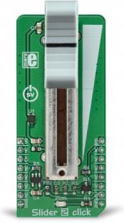
The Slider 2 click utilizes the PTA3043, a linear, high-grade, 10K potentiometer made by Bourns. This potentiometer has a 30 mm travel distance. The long travel distance of the wiper allows more accurate movements and combined with the high-quality manufacturing process it allows to dial-in the desired voltage with ease. This type of potentiometers are also known as sliders, thus the name for this Click board™. The potentiometer has a small dent in the middle, which enables tactile feedback when the center position is reached. The potentiometer is connected between the VREF and GND, acting as a voltage divider. Its wiper terminal outputs voltage in the range from 0 to 4.096V, depending on its position. The used potentiometer is linear, so the wiper potential changes linearly with its position.
.jpg)
The voltage reference(VREF) is obtained from the MCP1501, a high-precision voltage reference IC from Microchip. The main purpose of this IC is to provide and retain a very accurate voltage of 4.096V. Its voltage reference is accurate enough for most applications where the analog output from the Slider 2 click can be utilized as a control voltage signal (CV). The output is buffered with a rail-to-rail, low-power operational amplifier, labeled as OPA344, produced by Texas Instruments. After the buffering op-amp, the output signal is delivered at the AN pin of the mikroBUS, labeled as VO on this Click Board, so it can be easily sampled by the internal A/D converter of the host microcontroller unit (MCU.
Most MCUs have A/D peripherals that can use 4.096 as the reference voltage for the full-scale value (PIC 8-bit family is a good example). However, there are many cases where 2.048V is more adequate, so the Click board offers a choice: if there is a HIGH logic level at the RSL pin, the N-type MOSFET will open and another resistor will be introduced to the circuit. A voltage divider will be formed at the input of the buffering op-amp, which will halve the voltage from the potentiometer, reducing its maximum value to 2.048V. When the logic level at the RSL pin is LOW, the N-type MOSFET will stay closed, so the second resistor of the voltage divider remains isolated. This will cause the full voltage level from the potentiometer to appear at the VO pin of the Click Board, in the range from 0 to 4.096V max.
The MCP1501 IC has the #SHDN pin, used to shut down the IC when it's set to a LOW logic level. When this pin is set to a LOW logic level, the voltage reference output will be turned OFF, so there will be no voltage changes at the VO pin. By enabling the MCP1501 the voltage reference is established once again, so the Click Board can deliver an analog signal with the voltage ranging from 0 to 4.096V, or from 0 to 2.048V if the RSL pin is set to a HIGH logic level. It is recommended to start up the Click Board with the EN pin at the LOW logic level, to allow the internal power supply of the MCP1501 to reach its operational values.
Specifications
| Type |
ADC |
| Applications |
Slider 2 click can be used in any application that requires an analog control voltage, or it can be used to build HMI applications, adding them an accurate slider potentiometer. |
| On-board modules |
PTA3043, a linear 10K potentiometer with 30 mm travel distance, made by Bourns, Inc; MCP1501, a precise 4.096V voltage reference, by Microchip; OPA344, a low-power rail-to-rail operational amplifier, from Texas Instruments. |
| Key Features |
An accurate and precise slider with long travel distance of its wiper, a precise buffered voltage reference output which can be directly sampled by the integrated A/D section of the microcontroller, features a digitally selectable reference voltage (4.096V or 2.048V) to allow compliance with different MCU architecture. |
| Interface |
Analog,GPIO |
| Input Voltage |
5V |
| Compatibility |
mikroBUS |
| Click board size |
M (42.9 x 25.4 mm) |
Pinout diagram
This table shows how the pinout on Slider 2 Click corresponds to the pinout on the mikroBUS™ socket (the latter shown in the two middle columns).
| Notes |
Pin |
 |
Pin |
Notes |
|---|
| Analog Voltage OUT |
VO |
1 |
AN |
PWM |
16 |
RSL |
Ref. Voltage Selection |
| |
NC |
2 |
RST |
INT |
15 |
NC |
|
| MCP1501 Chip Enable |
EN |
3 |
CS |
RX |
14 |
NC |
|
| |
NC |
4 |
SCK |
TX |
13 |
NC |
|
| |
NC |
5 |
MISO |
SCL |
12 |
NC |
|
| |
NC |
6 |
MOSI |
SDA |
11 |
NC |
|
| |
NC |
7 |
3.3V |
5V |
10 |
5V |
Power supply |
| Ground |
GND |
8 |
GND |
GND |
9 |
GND |
Ground |
Onboard settings and indicators
| Label |
Name |
Default |
Description |
|---|
| LD1 |
PWR |
- |
Power LED indicator |
Software support
We provide a library for the Slider 2 click on our LibStock page, as well as a demo application (example), developed using MikroElektronika compilers. The demo can run on all the main MikroElektronika development boards.
Library Description
The library contains functions to enable or disable the chip and sets the maximum output voltage reference.
Key functions:
void slider2_enable(uint8_t state) - Function for enabling or disabling device
void slider2_setReference(uint8_t ref) - Function for setting max output voltage
void applicationTask()
{
    sliderValue = ADC1_Read(4);

    WordToHex(sliderValue, demoText);
    mikrobus_logWrite(" Slider value : 0x", _LOG_TEXT);
    mikrobus_logWrite(demoText, _LOG_LINE);
    Delay_ms( 500 );
}
The full application code, and ready to use projects can be found on our LibStock page.
Other mikroE Libraries used in the example:
Additional notes and information
Depending on the development board you are using, you may need USB UART click, USB UART 2 click or RS232 click to connect to your PC, for development systems with no UART to USB interface available on the board. The terminal available in all MikroElektronika compilers, or any other terminal application of your choice, can be used to read the message.
mikroSDK
This click board is supported with mikroSDK - MikroElektronika Software Development Kit. To ensure proper operation of mikroSDK compliant click board demo applications, mikroSDK should be downloaded from the LibStock and installed for the compiler you are using.
For more information about mikroSDK, visit the official page.