With the total height of 1.10mm, the BMA456 is well suited for using it in wearable and handheld devices. Its powerful event detection engine is equipped with a set of features suitable for a wearable device, including step detection and count, walking activity recognition, tilt on wrist, tap/double tap detection, and any motion pattern detection. The sensor can use any of its two interrupt pins to report a detected event. Accel 11 click can be used for a rapid development and testing of various applications based on step counting, fitness applications, profile switching and display ON/OFF applications, angle measurement applications, and similar applications.
How does it work?
Accel 11 click is based on the BMA456, a digital triaxial acceleration sensor from Bosch Sensortech. This sensor has many features perfectly suited for wearables, handheld, and IoT applications, offering a good balance between the performance and the power consumption. One of its key features is its extremely low power consumption, which makes it perfectly suited for such applications. There are several power modes which the BMA456 device can use. While in Low Power mode, the device consumes the least power, but the access to some features is restricted. More information can be found within the BMA456 datasheet.
.jpg)
The BMA456 sensor can measure acceleration within ranges of ±2 g, ±4 g, ±8, and ±16 g. It can output the measurement data using the Output Data Rate (ODR) from 0.78Hz (Low Power mode), up to 1600Hz (Performance mode). A high-precision analog front end facilitates highly sensitive MEMS, featuring a 16-bit A/D Converter. It allows very high accuracy of the output, even during very low amplitude changes. This makes the sensor particularly sensitive and accurate with movements that generate relatively low acceleration signals. However, using a highly sensitive MEMS makes the BMA456 prone to damage caused by extremely high g-forces (10,000 g for less than 200 µs).
Acceleration data is available in 16-bit format from both the data registers and the internal FIFO buffer of 1kb. The FIFO buffer can be used for more complex calculations or timed readings, reducing the traffic on the communication interface. The interrupt engine facilitates the FIFO buffer, triggering an interrupt for two FIFO events: watermark event, and FIFO buffer full event. FIFO buffer allows optimization within the firmware that runs on the host MCU.
Besides the acceleration MEMS and complementary analog front-end circuit, the BMA456 sensor also has an integrated temperature sensor. It is updated every 1.2s and sampled to an 8-bit value (complement of 2's format).
Interrupts can be triggered for many different events. Some basic events include the data-ready interrupt event and aforementioned FIFO events, while so-called feature engines can trigger an interrupt for any of the detected motion/movement events, including step detection/counter, activity recognition, tilt on wrist, tap/double tap, any/no motion, and error event interrupt. The extensive interrupt engine can use two programmable interrupt pins. Both of these pins can be assigned with any interrupt source and can be either LOW or HIGH on interrupt, depending on settings in appropriate registers. These two pins are routed to INT and AN pin of the mikroBUS™, and are labeled as IT1 and IT2, respectively.
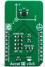
Accel 11 click offers two communication interfaces. It can be used with either I2C or SPI. The onboard SMD jumpers labeled as COMM SEL allow switching between the two interfaces. Note that all the jumpers have to be positioned either I2C or to SPI position. When I2C interface is selected, an additional SMD jumper labeled as ADDR SEL becomes available, determining the least significant bit of the BMA456 I2C address. The Click board™ should be interfaced only with MCUs that use logic levels of 3.3V.
Specifications
| Type |
Motion |
| Applications |
Accel 11 click can be used for a rapid development and testing of various applications based on step counting, fitness applications, profile switching and display ON/OFF applications, angle measurement applications, and similar applications. |
| On-board modules |
BMA456, a 16-bit triaxial acceleration sensor with ultra-low power consumption, from Bosch Sensortech. |
| Key Features |
Advanced interrupt engine allows detection of various events, ultra-low power consumption allows using in always-on wearable and handheld applications, thermal readings also available for increased reliability and accuracy. |
| Interface |
I2C,SPI |
| Input Voltage |
3.3V |
| Click board size |
M (42.9 x 25.4 mm) |
Pinout diagram
This table shows how the pinout on Accel 11 click corresponds to the pinout on the mikroBUS™ socket (the latter shown in the two middle columns).
| Notes |
Pin |
 |
Pin |
Notes |
|---|
| INT OUT 1 |
IT1 |
1 |
AN |
PWM |
16 |
NC |
|
| |
NC |
2 |
RST |
INT |
15 |
IT2 |
INT OUT 2 |
| SPI Chip Select |
CS |
3 |
CS |
RX |
14 |
NC |
|
| SPI Clock |
SCK |
4 |
SCK |
TX |
13 |
NC |
|
| SPI Data OUT |
SDO |
5 |
MISO |
SCL |
12 |
SCL |
I2C Clock |
| SPI Data IN |
SDI |
6 |
MOSI |
SDA |
11 |
SDA |
I2C Data |
| Power Supply |
3.3V |
7 |
3.3V |
5V |
10 |
NC |
|
| Ground |
GND |
8 |
GND |
GND |
9 |
GND |
Ground |
Accel 11 Click electrical specifications
| Description |
Min |
Typ |
Max |
Unit |
|---|
| Acceleration measurement range |
±2 |
- |
±16 |
g |
| Output refresh rate |
0.78 |
- |
1600 |
Hz |
| Sensitivity (±2g range to ±16g range) |
2048 |
- |
16384 |
LSB/g |
| Thermal measurement range |
-40 |
- |
+85 |
°C |
Onboard settings and indicators
| Label |
Name |
Default |
Description |
|---|
| LD1 |
PWR |
- |
Power LED indicator |
| JP1-JP4 |
COMM SEL |
Right |
Communication interface selection: right position I2C, left position SPI |
| JP5 |
ADDR SEL |
Left |
I2C address LSB selection: left position 0, right position 1 |
Software support
We provide a library for the Accel 11 click on our LibStock page, as well as a demo application (example), developed using MikroElektronika compilers. The demo can run on all the main MikroElektronika development boards.
Library Description
The library initializes and defines the I2C bus driver and drivers that offer a choice for writing data in register. The library includes function for read X/Y/Z axis data and function for read Temperature of the chip. The user also has the function for software reset and function for power on module.
Key functions:
void accel11_softwareReset() - Software reset.void accel11_powerOnProcedure() - Power On Procedure.int16_t accel11_getAxisData(uint8_t axis) - Accel Axis data.
Examples description
The application is composed of the three sections :
- System Initialization - Initializes I2C module.
- Application Initialization - Initialization driver init, software reset, power on module, test comunication and configuration sensor.
- Application Task - Reads X / Y / Z axis acceleration data and it logs to USBUART every 1500ms.
void applicationTask()
{
    char demoBuffer[ 50 ];
    int16_t X_axis;
    int16_t Y_axis;
    int16_t Z_axis;

    X_axis = accel11_getAxisData(_ACCEL11_ACCEL_X_AXIS);

    IntToStr(X_axis, demoBuffer);
    mikrobus_logWrite(" X axis : ", _LOG_TEXT);
    mikrobus_logWrite(demoBuffer, _LOG_LINE);

    Y_axis = accel11_getAxisData(_ACCEL11_ACCEL_Y_AXIS);

    IntToStr(Y_axis, demoBuffer);
    mikrobus_logWrite(" Y axis : ", _LOG_TEXT);
    mikrobus_logWrite(demoBuffer, _LOG_LINE);

    Z_axis = accel11_getAxisData(_ACCEL11_ACCEL_Z_AXIS);

    IntToStr(Z_axis, demoBuffer);
    mikrobus_logWrite(" Z axis : ", _LOG_TEXT);
    mikrobus_logWrite(demoBuffer, _LOG_LINE);

    mikrobus_logWrite("---------------------------------", _LOG_LINE);
    Delay_ms( 1500 );
}
The full application code, and ready to use projects can be found on our LibStock page.
Other mikroE Libraries used in the example:
Additional notes and informations
Depending on the development board you are using, you may need USB UART click, USB UART 2 click or RS232 click to connect to your PC, for development systems with no UART to USB interface available on the board. The terminal available in all MikroElektronika compilers, or any other terminal application of your choice, can be used to read the message.
mikroSDK
This click board is supported with mikroSDK - MikroElektronika Software Development Kit. To ensure proper operation of mikroSDK compliant click board demo applications, mikroSDK should be downloaded from the LibStock and installed for the compiler you are using.
For more information about mikroSDK, visit the official page.