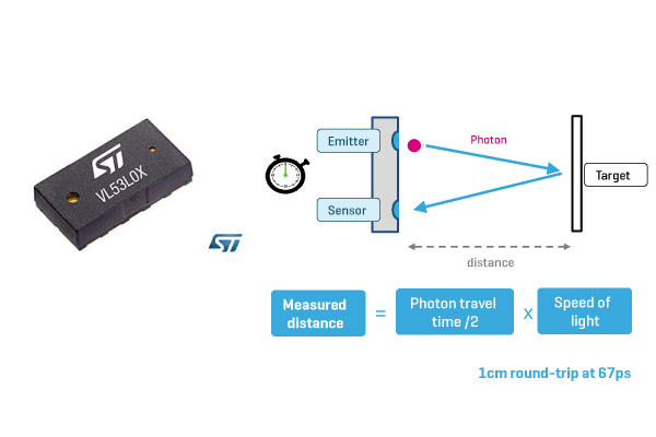
LightRanger 2 click carries VL53L0X IC from STMicroelectronics, the word's smallest Time-of-Flight ranging and gesture detector sensor. The click is designed to run on either 3.3V or 5V power supply. LightRanger 2 click communicates with the target microcontroller over I2C interface and the following pins on the mikroBUS™ line: RST, INT.
Measuring range
The VL53L0X sensor can measure absolute distances up to 2m. Reported range is independent of the target reflectance.
FlightSense™

The VL53L0X integrates a leading-edge SPAD array (Single Photon Avalanche Diodes) and embeds ST's second generation FlightSense™ patented technology.
FlightSense™ technology measures the time it takes for a photon to reach the nearest object. The photon travel time is multiplied by the speed of light, and from there a distance is calculated.
The photon travel time is not affected by reflectance, and this kind of technology is immune to ambient illumination and optical path variations.
VCSEL emitter
The VL53L0X's 940nm VCSEL emitter (Vertical Cavity Surface-Emitting Laser), is totally invisible to the human eye, coupled with internal physical infrared filters, it enables longer ranging distance, higher immunity to ambient light and better robustness to cover-glass optical cross-talk.
Power consumption
The average power consumption at 10MHz is 20mW, and while in standby mode the typical power consumption is around 5uA.
Specifications
| Type |
Proximity |
| Applications |
User detection for Personal Computers/ Laptops/Tablets and IoT devices, obstacle detection, distance measurement in applications, etc. |
| Key Features |
VL53L0X sensor, measures absolute range up to 2m, range is independent of the target reflectance, operates in high infrared ambient light levels |
| Key Benefits |
Equally sensitive to all objects regardless of color and reflectivity |
| Interface |
I2C,GPIO |
| Input Voltage |
3.3V or 5V |
| Compatibility |
mikroBUS |
| Click board size |
S (28.6 x 25.4 mm) |
Pinout diagram
This table shows how the pinout on LightRanger 2 click corresponds to the pinout on the mikroBUS™ socket (the latter shown in the two middle columns).
| Notes | Pin |  | Pin | Notes |
|---|
|
NC |
1 |
AN |
PWM |
16 |
NC |
|
| Enable |
EN |
2 |
RST |
INT |
15 |
INT |
Hardware interrupt |
|
NC |
3 |
CS |
TX |
14 |
NC |
|
|
NC |
4 |
SCK |
RX |
13 |
NC |
|
|
NC |
5 |
MISO |
SCL |
12 |
SCL |
I2C serial clock input |
|
NC |
6 |
MOSI |
SDA |
11 |
SDA |
I2C serial data |
| Power supply |
+3.3V |
7 |
3.3V |
5V |
10 |
+5V |
Power supply |
| Ground |
GND |
8 |
GND |
GND |
9 |
GND |
Ground |
Programming
The code initializes the click and sets it in continuous conversion mode. Range data is read continuously and printed on UART.
01      tof_init(true);
02      tof_set_timeout(500);
03      tof_start_continuous(0);
04      Uart_Write_Text("TOF readyrn");
05
06
07      while(1)
08      {
09         range = tof_read_range_continuous_millimeters();
10         WordToStr(range, txt);
11         Uart_Write_Text("Range: ");
12         Uart_Write_Text(txt);
13         Uart_Write_Text("rn");
14
15         if (tof_timeout_occurred())
16            Uart_Write_Text("TIMEOUTrn");
17
18      }

