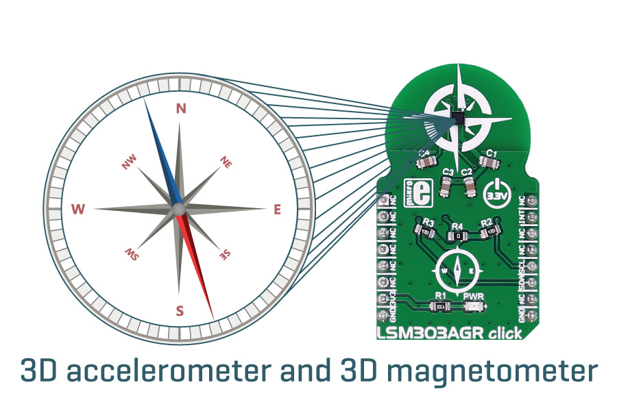
LSM303AGR click measures acceleration and magnetic field characteristics. It carries the LSM303AGR 3D accelerometer and 3D magnetometer. LSM303AGR click is designed to run on a 3.3V power supply. It communicates with the target microcontroller over I2C interface, with additional functionality provided by the INT pin on the mikroBUS™ line.
How the click works
The acceleration and magnetic field data is contained in the onboard chip’s registers, and it can be read out through I2C communication. You'll never lose your way with the LSM303AGR click by your side.

LSM303AGR microcontroller features
The LSM303AGR is an ultra-low-power high-performance system-in-package featuring a 3D digital linear acceleration sensor and a 3D digital magnetic sensor.
The sensor has linear acceleration full scales of ±2g/±4g/±8g/±16g and a magnetic field dynamic range of ±50 gauss.
The magnetic and accelerometer blocks can be enabled or put into power-down mode separately.
Accurate three-dimensional sensing
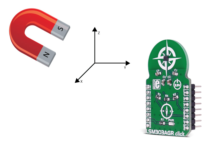
LMS303AGR click offers precise three-dimensional magnetic sensing. It detects the magnetic field in x,y, and z direction. With the low power consumption, it's ideally suited for small IoT projects and hand-held devices.

Specifications
| Type |
Magnetometer |
| Applications |
Digital compass applications, pedometers, display orientation, gaming and virtual reality input devices, etc. |
| MCU |
LSM303AGR |
| Key Features |
3 magnetic field channels and 3 acceleration
channels, ±50 gauss magnetic dynamic range, ±2/±4/±8/±16 g selectable acceleration full scales |
| Interface |
I2C |
| Power Supply |
3.3V |
| Compatibility |
mikroBUS |
| Click board size |
M (42.9 x 25.4 mm) |
Pinout diagram
This table shows how the pinout on LSM303AGR click corresponds to the pinout on the mikroBUS™ socket (the latter shown in the two middle columns).
| Notes | Pin |  | Pin | Notes |
|---|
|
NC |
1 |
AN |
PWM |
16 |
NC |
|
|
NC |
2 |
RST |
INT |
15 |
INT |
Magnetometer interrupt/data-ready signal |
|
NC |
3 |
CS |
TX |
14 |
NC |
|
|
NC |
4 |
SCK |
RX |
13 |
NC |
|
|
NC |
5 |
MISO |
SCL |
12 |
SCL |
I2C serial clock |
|
NC |
6 |
MOSI |
SDA |
11 |
SDA |
I2C serial data |
| Power supply |
+3.3V |
7 |
3.3V |
5V |
10 |
NC |
|
| Ground |
GND |
8 |
GND |
GND |
9 |
GND |
Ground |
Programming
Code examples for LSM303AGR click, written for MikroElektronika hardware and compilers are available on Libstock.
Code snippet
The following code snippet shows the initialization and reading of the sensor.
01 LSM303AGR_disableAcc();
02 LOG( "Accelerometer disablednr" );
03 LSM303AGR_setPowerMode( LSM303AGR_MAG, LSM303AGR_LOW_POWER );
04 LOG( "Magnetometer power mode set to low-powernr" );
05 LSM303AGR_setMeasureMode( LSM303AGR_CONT );
06 LOG( "Magnetometer measuring mode set to continuousnr" );
07 LSM303AGR_SetDataRate( LSM303AGR_MAG, 0x00 );
08 LOG( "Magnetometer data rate set to 10Hznr" );
09 LSM303AGR_readOutput( LSM303AGR_MAG, output );
10 LOG( "Reading magnetometer outputnr" );
11 Delay_ms( 200 );
12 WordToHex( output[0], txt );
13 LOG( "X: " );
14 LOG( txt );
15 WordToHex( output[1], txt );
16 LOG( "nrY: " );
17 LOG( txt );
18 WordToHex( output[2], txt );
19 LOG( "nrZ: " );
20 LOG( txt );
21 LOG( "nr" );

