Equipped with such powerful color sensor, this Click board™ can be used to detect a color intensity of the TFT display allowing high-quality image correction, it can be used for proximity detection, i.e. in a proximity of human skin, it can turn off the TFT display, thanks to specifically tailored proximity functions. Finally, it can use LEDs to illuminate an object, allowing it to be used in color recognition applications, even in low light conditions.
How does it work?
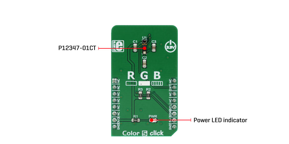
This Click board™ uses an integrated color and proximity sensor solution, labeled as P12347-01CT, from Hamamatsu company. It allows a range of functions, including color sensing, illumination, and proximity detection. It allows red, green, blue, and infra-red components (R, G, B, and IR) of the light to be converted into 16bit values, available via the I2C interface. All parameters of the internal sections can be configured via the I2C interface, providing control over measurement and detection. Each mode of operation (color sensing, proximity detection, and LED driving) has its own set of registers, allowing parameters for each mode to be configured. High integration of the sensor itself requires a minimum number of external components. Besides the sensor itself, the Click board™ uses only two additional pull-up resistors for I2C lines.
Proximity function is realized by emitting short pulses over the red LED and measuring the response. A current through the sensor is transformed into a frequency, and the internal counter is used to evaluate the resulting frequency. The results are stored on the output registers and available via the I2C. A LED pulse count number, LED driving current and proximity measurement cycle timings are all programmable, allowing full control over the proximity detection. During the inactivity period (between the measurement cycles) the device enters the standby mode, saving power. The proximity function remains active until the Sleep command is received.
Color sensing is performed with a single A/D converter. Therefore, the data is sampled consecutively, from each channel, and stored in internal buffers and after the integration period. It is then available via the I2C, on the output registers. The integration mode and time are configurable, allowing fine-tuning of the color sensing function. The color mode can be driven in Fixed or Manual mode. Manual mode performs one measurement, stores the data on the output registers, and reverts to a Sleep mode. When the Fixed mode is selected, the process is repeated cyclically, until the device receives either Sleep command.
The P12347-01CT integrated sensor uses consecutive pulses to drive R, G and B LED segments. The pulse width of each component can be set in 16 steps, but the complete LED driving cycle is fixed to 1.6 ms and the driving current is fixed at 8 mA. However, a low current mode is additionally available, using 1/10 of this current (0.8 mA), as well as the DC (Direct Current) mode, which allows programmable current intensity, from 8 mA up to 120 mA. In any case, the LED current limitations should be respected, given in the maximum rating table in the P12347-01CT datasheet. The proximity function remains active until the Sleep mode command is received.
The INT pin of the P12347-01CT sensor is routed to the mikroBUS™ INT pin, allowing proximity detection state to be reported to the host MCU. It can be used to generate an interrupt event on the MCU. It is driven to a HIGH in the event of proximity detection.
Specifications
| Type |
Optical |
| Applications |
It can be used for proximity detection, i.e. in proximity of human skin, it can turn off the TFT display, thanks to specifically tailored proximity functions. Finally, it can use LEDs to illuminate object, allowing it to be used in color recognition applications, even in low light conditions. |
| On-board modules |
P12347-01CT, a color and proximity sensor from Hamamatsu company |
| Key Features |
Color detection including the IR spectrum readings, in combination with proximity detection, perfectly suited to detect proximity of objects with human skin like properties. Three channel RGB LEDs allow for low light illumination and proximity detection. |
| Interface |
I2C |
| Input Voltage |
3.3V,5V |
| Click board size |
M (42.9 x 25.4 mm) |
Pinout diagram
This table shows how the pinout on Color 5 click corresponds to the pinout on the mikroBUS™ socket (the latter shown in the two middle columns).
| Notes | Pin |  | Pin | Notes |
|---|
|
NC |
1 |
AN |
PWM |
16 |
NC |
|
|
NC |
2 |
RST |
INT |
15 |
INT |
Interrupt |
|
NC |
3 |
CS |
RX |
14 |
NC |
|
|
NC |
4 |
SCK |
TX |
13 |
NC |
|
|
NC |
5 |
MISO |
SCL |
12 |
SCL |
I2C Clock |
|
NC |
6 |
MOSI |
SDA |
11 |
SDA |
I2C Data |
| Power supply |
3.3V |
7 |
3.3V |
5V |
10 |
5V |
|
| Ground |
GND |
8 |
GND |
GND |
9 |
GND |
Ground |
Onboard jumpers and settings
| Label | Name | Default | Description |
|---|
| PWR |
PWR |
- |
Power LED indicator |
Software support
We provide a library for the Color_5 Click on our LibStock page, as well as a demo application (example), developed using MikroElektronika compilers. The demo can run on all the main MikroElektronika development boards.
Library Description
The library initializes and defines the I2C bus driver and drivers that offer a choice for writing data in the register. The library includes a function to read the color through a red, green, and blue filter and IR data. The user can set the color of the LEDs. The sensor has a proximity mode with which it can detect the object in front of the sensor. The user has a function for reading light through one filter as well as reading the light through all the filters.
Key functions:
void color5_setConfiguration(uint8_t reg, uint8_t _data) - Functions for configuration sensor
void color5_setLedDriver(uint8_t red, uint8_t green, uint8_t blue) - Functions for setting led color
uint16_t color5_readData(uint8_t reg) - Functions for reading data from register
uint8_t color5_getInterrupt() - Functions for proximity detect
Example description
The application is composed of three sections :
- System Initialization - Initializes I2C module
- Application Initialization - Initializes driver init and configuration proximity and led driver
- Application Task - (code snippet) - Reads the color values through a red, blue, green filter and IR data. Checking that the proximity sensor detects the object.
void applicationTask()
{
 // Color init
 color5_setConfiguration(_COLOR5_REG_RGB_SENSOR_CTRL,_COLOR5_CFG_SENSOR_RESET | _COLOR5_CFG_MANUAL_SETTINGS_MODE );
 color5_setConfiguration(_COLOR5_REG_RGB_SENSOR_CTRL, _COLOR5_CFG_LOW_GAIN | _COLOR5_CFG_MANUAL_SETTINGS_MODE );

 RED_Data = color5_readData( _COLOR5_REG_OUT_DATA_RED_MSB );
 IntToStr( RED_Data, dataTxt );
 mikrobus_logWrite( "RED data : ", _LOG_TEXT );
 mikrobus_logWrite( dataTxt, _LOG_TEXT );
 mikrobus_logWrite( " nm", _LOG_LINE );

 GREEN_Data = color5_readData( _COLOR5_REG_OUT_DATA_GREEN_MSB );
 IntToStr( GREEN_Data, dataTxt );
 mikrobus_logWrite( "GREEN data : ", _LOG_TEXT );
 mikrobus_logWrite( dataTxt, _LOG_TEXT );
 mikrobus_logWrite( " nm", _LOG_LINE );

 BLUE_Data = color5_readData( _COLOR5_REG_OUT_DATA_BLUE_MSB );
 IntToStr( BLUE_Data, dataTxt );
 mikrobus_logWrite( "BLUE data : ", _LOG_TEXT );
 mikrobus_logWrite( dataTxt, _LOG_TEXT );
 mikrobus_logWrite( " nm", _LOG_LINE );

 IR_Data = color5_readData( _COLOR5_REG_OUT_DATA_IR_MSB );
 IntToStr( IR_Data, dataTxt );
 mikrobus_logWrite( "IR data : ", _LOG_TEXT );
 mikrobus_logWrite( dataTxt, _LOG_TEXT );
 mikrobus_logWrite( " nm", _LOG_LINE );

 mikrobus_logWrite("---------------rn", _LOG_LINE);


 if (color5_getInterrupt() == 1)
 {
 mikrobus_logWrite("Proximity detect", _LOG_LINE);
 }
 Delay_ms( 500 );
}
The full application code, and ready to use projects can be found on our
LibStock page.
Other mikroE Libraries used in the example:
Additional notes and information
Depending on the development board you are using, you may need USB UART click, USB UART 2 click or RS232 click to connect to your PC, for development systems with no UART to USB interface available on the board. The terminal available in all MikroElektronika compilers, or any other terminal application of your choice, can be used to read the message.
mikroSDK
This click board is supported with mikroSDK - MikroElektronika Software Development Kit. To ensure proper operation of mikroSDK compliant click board demo applications, mikroSDK should be downloaded from the LibStock and installed for the compiler you are using.
For more information about mikroSDK, visit the official page.