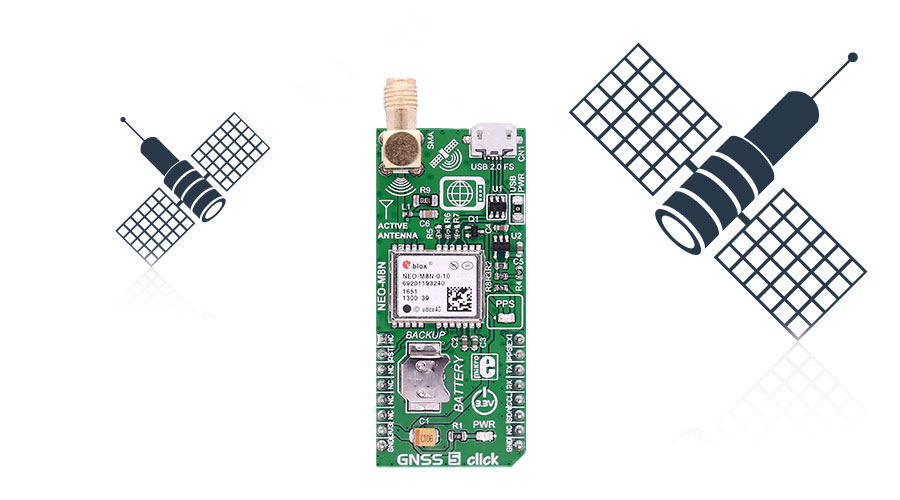
Determine your current position with GNSS 5 click. It carries the NEO-M8N GNSS receiver module from u-blox. GNSS 5 click is designed to run on a 3.3V power supply. The click communicates with the target microcontroller over I2C or UART interface, with additional functionality provided by the following pins on the mikroBUS line: RST, INT, PWM.
A USB interface (micro USB port), which is compatible with the USB version 2.0 FS (Full Speed, 12 Mbit/s), can be used for communication as an alternative to the UART.
The USB port can be used as a power supply as well if you need the click board to be a standalone device.
NEO-M8N GNSS receiver module features
The NEO-M8 series of concurrent GNSS modules are built on the high performing u-blox M8 GNSS engine in the industry proven NEO form factor.
The NEO-M8 series utilizes concurrent reception of up to three GNSS systems (GPS/Galileo together with BeiDou or GLONASS), recognizes multiple constellations simultaneously and provides outstanding positioning accuracy in scenarios where urban canyon or weak signals are involved.
The u-blox NEO-M8 modules can also benefit from the u-blox AssistNow assistance service. The Online service provides GNNS broadcast parameters, e.g. ephemeris, almanac plus time or rough position to reduce the receiver's time to first fix significantly and improve acquisition sensitivity.
Hardware Backup Mode - If the main supply voltage fails, and a battery is connected to V_BCKP, parts of the receiver switch off, but the RTC still runs providing a timing reference for the receiver. This operating mode enables all relevant data to be saved in the backup RAM to allow a hot or warm start later.
What is GNSS?
GNSS stands for Global Navigation Satellite System, an umbrella term that describes both the United States GPS, the Russian GLONASS global positioning systems, and European Galileo.
How it works
A constellation of satellites sends a continuous signal towards Earth. Onboard every satellite is an atomic clock, and all of them are synchronized, thanks to a reference time scale defined by the whole system. So, that the signals coming from the different satellites of the same constellation share the same reference time scale.

If the user wants to utilize GNSS to determine a position, they must have an antenna that receives the signals coming from the satellites, and a receiver that translates these signals. The antenna position will be deduced from the measurements of the time delay between the emission time (satellite) and the reception time (receiver) for at least 4 signals coming from different satellites.
Specifications
| Type |
GPS/GNSS |
| Applications |
Asset tracking, for navigation devices based on GPS and GLONASS, road navigation devices, public transport, wearable devices, etc. |
| On-board modules |
NEO-M8N GNSS receiver module from u-blox |
| Key Features |
-167 dBm navigation sensitivity, supports all satellite augmentation systems, battery holder |
| Interface |
I2C or UART |
| Input Voltage |
3.3V |
| Click board size |
L (57.15 x 25.4 mm) |
Pinout diagram
This table shows how the pinout on GNSS 5 click corresponds to the pinout on the mikroBUS socket (the latter shown in the two middle columns).
| Notes | Pin |  | Pin | Notes |
|---|
|
NC |
1 |
AN |
PWM |
16 |
EXI |
External Interrupt (input). Can be used for wake-up functions in Power Save Mode |
| Reset module |
RESET |
2 |
RST |
INT |
15 |
PPS |
Pulse-Per-Second (by default, it is configurable on different time bases) |
|
NC |
3 |
CS |
TX |
14 |
RX |
UART receive |
|
NC |
4 |
SCK |
RX |
13 |
TX |
UART transmit |
|
NC |
5 |
MISO |
SCL |
12 |
SCL |
SCL I2C line |
|
NC |
6 |
MOSI |
SDA |
11 |
SDA |
SDA I2C line |
| Power supply |
+3.3V |
7 |
3.3V |
5V |
10 |
NC |
|
| Ground |
GND |
8 |
GND |
GND |
9 |
GND |
Ground |
Buttons and LEDs
| Designator | Name | Type | Description |
|---|
| LD1 |
PWR |
LED |
Power Indication LED |
| LD2 |
PPS |
LED |
Pulse Per Second (by default) when the GNSS receiver has established a connection with the satellite constellation the LED starts blinking |
Programming
Code examples for GNSS 5 click, written for MikroElektronika hardware and compilers are available on Libstock.
Code snippet
The following code snippet shows the function that feeds the data into a buffer until the sentence is ready for parsing, and sets the appropriate flag when such event occurs.
01 void gnss_put( char input )
02 {
03    static bool sentence_flag;
04
05    if( ( input != 'r' && input != 'n' ) && buffer_position < BUFFER_MAX )
06    {
07        buffer[ buffer_position++ ] = input;
08    }
09    else if( input == 'r' )
10    {
11        sentence_flag = true;
12    }
13    else if( input == 'n' && sentence_flag )
14    {
15        buffer[ buffer_position ] = '';
16        buffer_position = 0;
17        strcpypvt( process_buffer, buffer );
18        sentence_flag = false;
19        process_flag = true;
20    }
21    else
22    {
23        buffer_position = 0;
24    }
25 }

