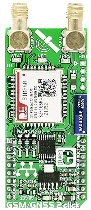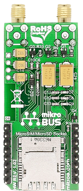

GSM/GNSS 2 click combines GPS/GLONASS location tracking with GSM module capability for mobile communication. The click carries SIM868 quad-band GSM/GPRS module.
GSM/GNSS 2 click is designed to run on either 3.3V or 5V power supply. It communicates with the target MCU over UART interface with additional functionality provided by the following pins on the mikroBUS™ line: AN, RST, CS, PWM, INT.
When connected to a GPS antenna, it can receive GPS coordinates, time, and other information from orbiting satellites.
SIM868 module features
SIM868 is integrated with a high-performance GSM/GPRS engine and a GNSS engine.
Quad-band frequencies
SIM868 is a quad-band GSM/GPRS module that works on frequencies GSM 850MHz, EGSM 900MHz, DCS 1800MHz and PCS 1900MHz.
SIM868 features GPRS multi-slot class 12/class 10 (optional) and supports the GPRS coding schemes CS-1, CS-2, CS-3 and CS-4. The GNSS solution offers best-in-class acquisition and tracking sensitivity, Time-To-First-Fix (TTFF) and accuracy.
Power consumption
SIM868 is designed with a power saving technique so that the current consumption is as low as 0.65mA in sleep mode (with GNSS engine powered down).
GPS and GLONASS
GNSS stands for Global Navigation Satellite System, an umbrella term that describes both the United States GPS and the Russian GLONASS global positioning systems. GLONASS is an acronym for Globalnaya Navigatsionnaya Sputnikovaya Sistema (Global Navigation Satellite System).
GPS currently has 33 satellites in orbit, and GLONASS has 24. This two-constellation system is particularly suitable for urban areas with high-rise buildings and complex environments.
GLONASS is suited for usage in high latitudes (north or south), where getting a GPS signal can be difficult.
Specifications
| Type |
GSM+GPS,2G GPRS |
| Applications |
Navigation, surveying and mapping, asset tracking, etc. |
| On-board modules |
SIM868 Quad-Band GSM/GPRS module |
| Key Features |
GPS antenna connector, GNSS antenna connector, SIM card socket |
| Interface |
GPIO,UART |
| Compatibility |
mikroBUS |
| Click board size |
L (57.15 x 25.4 mm) |
| Input Voltage |
3.3V or 5V |
Pinout diagram
This table shows how the pinout on GSM/GNSS 2 click corresponds to the pinout on the mikroBUS™ socket (the latter shown in the two middle columns).
| Notes |
Pin |
 |
Pin |
Notes |
|---|
| SIM card detection |
DET |
1 |
AN |
PWM |
16 |
RING |
Ring indicator |
| SIM reset |
RST |
2 |
RST |
INT |
15 |
CTS |
Clear to send |
| Request to send |
RTS |
3 |
CS |
TX |
14 |
TXD |
Transmit data |
| |
NC |
4 |
SCK |
RX |
13 |
RXD |
Receive data |
| |
NC |
5 |
MISO |
SCL |
12 |
NC |
|
| |
NC |
6 |
MOSI |
SDA |
11 |
NC |
|
| Power supply |
+3.3V |
7 |
3.3V |
5V |
10 |
+5V |
Power supply |
| Ground |
GND |
8 |
GND |
GND |
9 |
GND |
Ground |
Maximum ratings
| Description |
Min |
Typ |
Max |
Unit |
|---|
| Supply Voltage |
3.4 |
|
4.4 |
V |
| Normal operation: |
-40 |
|
+85 |
°C |
| Support SIM card: |
|
1.8V, 3V |
|
|
| I[VBAT] |
|
2 |
|
A |
Programming
Code examples for GSM/GNSS 2 click, written for MikroElektronika hardware and compilers are available on Libstock.
Code snippet
This code snippet initializes the MCU and the module. It first sends an initial message to the user and then logs an events such as calls or messages on the microSD card and reads the current GPS location, all in an infinite loop.
01 void main( void )
02 {
03     system_init();
04     at_init( rsp_handler, UART1_Write, buffer, sizeof( buffer ) );
05     at_cmd_save( "+CMS ERROR", 1000, NULL, NULL, NULL, at_cb_send_init_message );
06     at_cmd_save( "+FSMEM", 3000, NULL, NULL, NULL, at_cb_microsd_end );
07     at_cmd_save( "+CMT", 3000, NULL, NULL, NULL, sms_action_handler );
08     at_cmd_save( "+CMGS", 1000, NULL, NULL, NULL, at_cb_send_init_message );
09
10     gsm_gnss_2_power_on();
11
12     gsm_gnss_2_init();
13
14     send_SMS();                               // Sending initial message
15
16     while( !msg_sent ) at_process();          // Waiting for SMS sending status
17
18     LOG( "rn**********************************************************rn" );
19     LOG( "Finished Sending SMS Message.");
20     LOG( "rn**********************************************************rn" );
21
22     micro_SD();                               // Creating files on microSD
23
24     while( !sd_f ) at_process();              // Waiting for SD card operations
25
26     LOG( "rn**********************************************************rn" );
27     LOG( "Finished SD Initialization.");
28     LOG( "rn**********************************************************rn" );
29     Delay_ms( 1000 );
30
31     LOG( "rn**********************************************************rn" );
32     LOG( "Waiting for the Message or Call in an Infinite Loop");
33     LOG( "rn**********************************************************rn" );
34
35
36     while( true )
37     {
38         at_process();
39
40         if ( action_f )                       // Message received or call ended
41         {
42             update_log();
43             action_f = false;
44         }
45     }
46
47 }
Resources
Downloads

