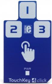
Touch Key 4 click is a capacitive touch sensing Click board™, with the advanced touch/proximity sensor IC. It has three independently configurable channels and can work in several operating modes, including multiple button pattern detection mode, combo mode, press and hold detection mode, power button mode, and more. Capacitive touch sensor inputs are protected from false detection, which can be caused by the noise and RF interferences, providing a very reliable touch sensing functionality. Electrostatic Discharge (ESD) protection up to 8kV ensures that no ESD failures will ever occur while interacting with the sensor surface.
Equipped with three sensor channels, which are compensated for parasitic capacitances of the system, have an automatic recalibration feature, and are protected against ESD up to 8kV, Touch Key 4 click offers very reliable and accurate sensing for any application that uses capacitive touch sensing functions, such as desktop or notebook computers, LCD/TFT monitors, various types of consumer electronics, home appliances, and other applications that can benefit of having a reliable and feature-rich touch activated user interface.
How does it work?
The capacitive sensor IC used on the Touch Key 4 click is the CAP1293, 3 channel capacitive touch sensor with proximity detection, from Microchip. This IC has three independently configurable capacitive touch channels with the auto-calibration function. It uses the I2C protocol for the communication, with the I2C bus pins routed to the respective mikroBUS™ pins: SMCLK is the I2C clock pin, routed to the SCK pin of the mikroBUS™ and the SMDATA is the I2C data pin, routed to the SDA pin of the mikroBUS™. Additionally, there is an #ALERT pin routed to the mikroBUS™ INT pin, which allows interrupts to be triggered on the host MCU.
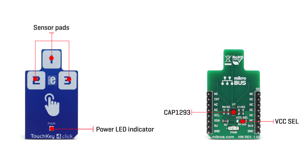
The click board itself has three PCB pads, used to sense touch or proximity events. These pads are the only elements on the top side of the board, allowing installation of the protective acrylic glass layer. The capacitive sensor channels feature programmable sensitivity threshold and an automatic recalibration, used to compensate for environmental changes. The device can work in several power modes, having separate input settings for the Active and Standby mode. The recalibration procedure can be triggered either automatically, or on-demand, and it is used to set the base register value for the “not touched†state of the input channel.
The CAP1293 IC also integrates sections that provide an efficient interference protection. The EMI and RFI detection sections provide protection by discarding the corrupted bytes if the detected noise threshold is exceeded. Also, false input readings, such as the negative values and “stuck button†events are handled by the internal algorithms, which will set the respective bits to indicate the problem, and can be set to trigger a recalibration procedure.
There are three power modes of operation:
- Fully Active mode, which monitors all the enabled input channels in cyclic order. Touch detection threshold can be individually set for each channel, and the averaging (integration) and cycle time are set via the appropriate register. All registers are available for both reading and writing.
- Standby mode, which cycles through the channels, enabled by the dedicated Standby Channel Register. There is only one threshold for all the enabled channels, determined by the dedicated Standby Threshold Register. Communication will be still functional and the device can be set to a Fully Active mode. This mode uses less power than the Fully Active mode, depending on the settings of the cycle time and integration time.
- Combo mode, which is a mixture of the Active and Standby modes. The device cycles through both the channels enabled in the Active mode, as well as the inputs enabled in the Standby mode. This mode allows mixture between proximity and touch detection, as it has two separate gain level registers - one register controls gain for the Active mode enabled channels, while the other register is for the Standby mode enabled channels.
- Deep Sleep mode, which consumes the least power. In this mode, all the input channels are disabled. The communication is still possible. As soon as the communication ends, the device reverts to Deep Sleep mode, if not instructed otherwise.
In general, the device always reverts to a power saving mode when idling. If the programmed cycling time through all the enabled channels is long enough, the sampling of all the enabled channels will be finished before the cycle ends. When this happens, the device will revert to a power saving mode, waiting for another cycle to begin. If there is not enough time to sample all the channels, the device will not revert to a power saving mode. This will affect the overall power consumption.
Multiple touch pattern detection (MTPD) is used to set the pattern which will generate a touch event. This pattern may consist of multiple specific sensors touched at once, a minimal number of touched sensors, or when their noise flag bit is set in the status register. This function can be used to detect a closed lid or similar event.
The interrupt engine allows to differentiate between the simple touch and touch and hold events. The interrupt can be generated once when a pad touch is detected/released, or it can be repeatedly generated while the pad is touched. A special case of touch detection is the Power Button mode. This mode requires the button to be held pressed for a programmed interval of time before an interrupt is generated. This allows for a simple Power Button functionality to be implemented in any application. The interrupt can be generated for various other events, such as the failure to calibrate event and similar auxiliary events.
The press and hold mode is very useful for developing volume control type of applications. The programmable interval timer is started after the first touch event on a specific channel, and if no release event is detected after the timer expires, the interrupt is generated, in the programmed intervals. This can be used to implement volume up/down buttons, light dimming buttons, and similar applications.
Any interrupt event will drive the #ALERT pin to a LOW logic state. This pin is routed to the mikroBUS™ INT pin and it is used to trigger an interrupt event on the host MCU.
More information about the registers and their functions can be found in the CAP1293 IC datasheet. However, the provided click library offers a function for easy and simple control of the Touch Key 4 click. The provided application example demonstrates their functionality and it can be used as a reference for custom projects.
Specifications
| Type |
Capacitive |
| Applications |
Desktop or notebook computers control, LCD/TFT monitors, various types of consumer electronics, home appliances, and other applications that can benefit of having a reliable and feature-rich touch activated user interface. |
| On-board modules |
CAP1293, a 3 channel capacitive touch sensor with proximity detection, from Microchip |
| Key Features |
Reliable capacitive touch detection based on the RightSense® technology, noise filtering, three input channels, press and hold function, power button function, automatic recalibration and programmable sensitivity for each channel |
| Interface |
I2C |
| Input Voltage |
3.3V or 5V |
| Click board size |
M (42.9 x 25.4 mm) |
Pinout diagram
This table shows how the pinout on Touch Key 4 click corresponds to the pinout on the mikroBUS™ socket (the latter shown in the two middle columns).
| Notes | Pin |  | Pin | Notes |
|---|
|
NC |
1 |
AN |
PWM |
16 |
NC |
|
|
NC |
2 |
RST |
INT |
15 |
INT |
Interrupt |
|
NC |
3 |
CS |
RX |
14 |
NC |
|
|
NC |
4 |
SCK |
TX |
13 |
NC |
|
|
NC |
5 |
MISO |
SCL |
12 |
SCL |
I2C Clock |
|
NC |
6 |
MOSI |
SDA |
11 |
SDA |
I2C Data |
| Power supply |
+3.3V |
7 |
3.3V |
5V |
10 |
+5V |
Power supply |
| Ground |
GND |
8 |
GND |
GND |
9 |
GND |
Ground |
Onboard settings and indicators
| Label | Name | Default | Description |
|---|
| LD1 |
PWR |
- |
Power LED indicator |
| JP1 |
VCC SEL. |
Right |
Power supply voltage selection: right position 3V3, left position 5V |
Software support
We provide a library for Touch Key 4 click on our Libstock page, as well as a demo application (example), developed using MikroElektronika compilers and mikroSDK. The provided click library is mikroSDK standard compliant. The demo application can run on all the main MikroElektronika development boards.
Library Description
The library initializes and defines I2C bus driver and driver functions which offer a choice to write data in the registers and to read data from the registers. The library also offers a choice to detect a touch on enabled sensor inputs in two possible modes, Active and Standby mode.
Every sensor input can be configured to work in both modes at the same time (Combo mode). The sensor inputs can also be configured to detect when touch is released and can generate an interrupt as long as the touch is detected. For more details check the documentation.
Key functions:
void touchkey4_writeReg( const uint8_t register_address, const uint8_t transfer_data ) - The function writes one-byte data in the register.
void touchkey4_readReg( const uint8_t register_address, uint8_t *dataOut, const uint8_t nBytes ) - The function reads data from the register.
void touchkey4_detectTouch( uint8_t *inputSens ) - The function detects a touch on the sensor inputs and checks if touch is detected or if touch is released.
void touchkey4_setComboMode( const uint8_t analogGain, const uint8_t enInput1, const uint8_t enInput2, const uint8_t enInput3 ) - Function puts
the device in Combo mode (Active and Standby) and enables desired inputs in Active mode, Standby mode or both modes.
Examples Description
- System Initialization - Initializes peripherals and pins.
- Application Initialization - Initializes I2C driver and sets configuration for TouchKey 4 click. TouchKey 4 is configured to works in Combo mode (Active and Standby mode). Input 1 is enabled in Active mode, input 3 is enabled in Standby mode, and input 2 is enabled to works in both modes. In this example, the interrupt will be generated when touch is detected and when touch is released. Also, input 2 will generate an interrupt as long as the touch is detected (press and hold the event), while input 1 and input 3 will generate interrupt only once on one touch detection, after which the touch will be released. Note: Standby mode should be used when fewer sensor inputs are enabled, and when they are programmed to have more sensitivity.
- Application Task - (code snippet) - Calls function to check touch detection (is interrupt occurred) and shows a message on USB UART if touch is detected or if touch is released on enabled inputs.
void applicationTask()
{
 touchkey4_detectTouch( &sensorResults[0] );
 for (cnt = 0; cnt < 3; cnt++)
 {
 if (sensorResults[ cnt ] == 1)
 {
 if (cnt == 0)
 mikrobus_logWrite( "Input 1 is touched", _LOG_LINE );
 else if (cnt == 1)
 mikrobus_logWrite( "Input 2 is touched", _LOG_LINE );
 else
 mikrobus_logWrite( "Input 3 is touched", _LOG_LINE );
 }
 else if (sensorResults[ cnt ] == 2)
 {
 if (cnt == 0)
 mikrobus_logWrite( "Input 1 is released", _LOG_LINE );
 else if (cnt == 1)
 mikrobus_logWrite( "Input 2 is released", _LOG_LINE );
 else
 mikrobus_logWrite( "Input 3 is released", _LOG_LINE );
 mikrobus_logWrite( "", _LOG_LINE );
 }
 }
}
The full application code, and ready to use projects can be found on our Libstock page.
Other mikroE Libraries used in the example:
Additional notes and information
Depending on the development board you are using, you may need USB UART click, USB UART 2 click or RS232 click to connect to your PC, for development systems with no UART to USB interface available on the board. The terminal available in all MikroElektronika compilers, or any other terminal application of your choice, can be used to read the message.
mikroSDK
This click board is supported with mikroSDK - MikroElektronika Software Development Kit. To ensure proper operation of mikroSDK compliant click board demo applications, mikroSDK should be downloaded from the LibStock and installed for the compiler you are using.
For more information about mikroSDK, visit the official page.