The features such as the support for the 16-bit data output, high sensitivity and wide measurement range all make this sensor a perfect choice for various IoT applications. The internal 16-bit ADC, voltage reference and signal processing units makes the Click board™ a very accurate spatial magnetic sensor, perfectly suited for the development of various position sensing applications, contactless knobs, encoders, switches, and potentiometers, or some other type of magnetic field measuring application, based on an accurate spatial sensing.
How does it work?
3D Hall 7 click carries the AK09970N, a low power 3D magnetic sensor, from AsahiKASEI (AKM). This sensor relies on a Hall effect to accurately sense magnetic field changes on three perpendicular axes. The internal magnetic field sensing elements are multiplexed and connected to a pre-amplifier and then to a 16bit low noise Analog to Digital Converter (ADC), which sequentially samples each sensor, providing 16-bit spatial data over the digital interface.

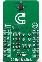
The magnetic sensor has a very low pin count. Therefore, SPI and I2C lines are multiplexed on the same pins. In order to allow functionality for both SPI and I2C interfaces, 3D Hall 7 click have onboard jumpers for communication interface selection. Thus, the communication interface selection procedure relies on switching the appropriate SMD jumpers, named COMM SEL. Note that all of the I2C/SPI group jumpers need to be switched at the same side: all three should either be soldered as I2C or SPI. If one of them shows in the opposite position from the rest, the communication with the IC might not be possible.
The power consumption is a big concern as of lately, with the introduction of the IoT. The ability to work in a low power mode is a must for every device which is to be used for any type of IoT networking. The AK09970N magnetic sensor features power down mode, single measurement mode and seven continuous measurement modes, allowing the user to make a perfect balance between sampling frequency, measurement accuracy and power consumption. The power consumption is in a close relationship with the data output refresh rate (ODR).
The AK09970N magnetic sensor also features a powerful programmable interrupt engine, which allows many event sources to be signaled via the two interrupt pins (INT and ODINT), which are routed from the sensor to the mikroBUS™ INT and AN pins respectively. A very useful function of the interrupt engine is the signaling of the data ready event. That way, the host MCU does not have to poll the sensor for the data acquisition. The sensor can simply trigger an interrupt when the data is ready for reading. The interrupt engine allows some other customizations of the interrupt signal, such as the magnetic sensor overflow, ADC overflow and Switch event.
The sensor provides raw data output, based on a strength of the magnetic field. The measurement is affected by many factors: slight manufacturing differences between ICs affect the readings, even the slight differences between Hall plates within the same IC might affect the accuracy, although the IC contains highly matched sensing elements. Also, the altitude might affect the readings, as well as temperature changes. Therefore, the IC is equipped with the temperature independent reference voltage, thus minimizing the influence the mentioned unwanted factors.
The power mode, output data rate, interrupt thresholds for each axis, and other working parameters, including the availability of the I2C interface, are contained within the configuration registers of the AK09970N magnetic sensor. The sensor is highly configurable, with many configuration options. The AK09970N datasheet contains an in-depth explanation of all the registers and their functionality. However, 3D Hall 7 software library contains simplified functions that allow straight-forward readings to be performed, reducing the steps needed for a proper initialization and configuration of the device.
The Click board™ can operate with 3.3V MCUs only, it is set to work over the I2C by default, and it is already equipped with the pull-up resistors. It is ready to be used as soon as it is inserted into a mikroBUS™ socket of the development system.
Specifications
| Type |
Magnetic |
| Applications |
It is well-suited for development of various position sensing applications, contactless knobs, encoders, switches, and potentiometers, or some other type of magnetic field measuring application, based on an accurate spatial sensing. |
| On-board modules |
AK09970N, a low power 3D magnetic sensor, from AsahiKASEI (AKM); |
| Key Features |
The three independent Hall sensor channels allow high accuracy, additional thermal sensor for compensation. The small package case allows a very compact design while offering plenty of features, a programmable interrupt engine, extremely low power consumption, and more |
| Interface |
I2C,SPI |
| Input Voltage |
3.3V |
| Click board size |
M (42.9 x 25.4 mm) |
Pinout diagram
This table shows how the pinout on 3D Hall 7 click corresponds to the pinout on the mikroBUS™ socket (the latter shown in the two middle columns).
| Notes |
Pin |
 |
Pin |
Notes |
|---|
| Interrupt 2 |
IT2 |
1 |
AN |
PWM |
16 |
NC |
|
| Reset |
RST |
2 |
RST |
INT |
15 |
IT1 |
Interrupt 1 |
| SPI Chip Select |
CS |
3 |
CS |
RX |
14 |
NC |
|
| SPI Clock |
SCK |
4 |
SCK |
TX |
13 |
NC |
|
| SPI SDO |
SDO |
5 |
MISO |
SCL |
12 |
SCL |
I2C Clock |
| SPI SDI |
SDI |
6 |
MOSI |
SDA |
11 |
SDA |
I2C Data |
| Power Supply |
3.3V |
7 |
3.3V |
5V |
10 |
NC |
|
| Ground |
GND |
8 |
GND |
GND |
9 |
GND |
Ground |
Onboard settings and indicators
| Label |
Name |
Default |
Description |
|---|
| LD1 |
PWR |
- |
Power LED Indicator |
| JP1-JP4 |
COMM SEL |
Right |
Communication interface selection: left position SPI, right position I2C |
| JP5 |
ADDR SEL |
Left |
I2C address selection |
Software support
We provide a library for the 3D Hall 7 click on our LibStock page, as well as a demo application (example), developed using MikroElektronika compilers. The demo can run on all the main MikroElektronika development boards.
Library Description
The library initializes and defines the I2C bus or SPI bus driver and drivers that offer a choice for writing data in register and reads data from register. The library includes function for read magnetics X/Y/Z axis data, configuration device, reads interrupt states and device info(company ID and device ID).
Key functions:
void c3dhall7_getAxisData( T_C3DHall 7_AXIS *axis) - Get Axis data.void c3dhall7_configuration(uint8_t reg, uint16_t dataIn) - Configuration function.
Examples description
The application is composed of the three sections :
- System Initialization - Initializes I2C or SPI module and all the necessary GPIO pins.
- Application Initialization - Initializes driver init, test communication and configuration device for measurement.
- Application Task - Reads 3 Axis of the magnetic sensor and logs this data to USBUART every 500ms.
void applicationTask()
{
    char demoText[ 50 ];

    c3dhall7_getAxisData(&axis);

    mikrobus_logWrite("---- Measurement data of magnetic sensor ----", _LOG_LINE);
    IntToStr(axis.x, demoText);
    mikrobus_logWrite("** X axis: ", _LOG_TEXT);
    mikrobus_logWrite(demoText, _LOG_LINE);

    IntToStr(axis.y, demoText);
    mikrobus_logWrite("** Y axis: ", _LOG_TEXT);
    mikrobus_logWrite(demoText, _LOG_LINE);

    IntToStr(axis.z, demoText);
    mikrobus_logWrite("** Z axis: ", _LOG_TEXT);
    mikrobus_logWrite(demoText, _LOG_LINE);

    mikrobus_logWrite("---------------------------------------------", _LOG_LINE);
    Delay_ms( 500 );
}
The full application code, and ready to use projects can be found on our LibStock page.
Other mikroE Libraries used in the example:
Additional notes and informations
Depending on the development board you are using, you may need USB UART click, USB UART 2 click or RS232 click to connect to your PC, for development systems with no UART to USB interface available on the board. The terminal available in all MikroElektronika compilers, or any other terminal application of your choice, can be used to read the message.
mikroSDK
This click board is supported with mikroSDK - MikroElektronika Software Development Kit. To ensure proper operation of mikroSDK compliant click board demo applications, mikroSDK should be downloaded from the LibStock and installed for the compiler you are using.
For more information about mikroSDK, visit the official page.