 |

|
|
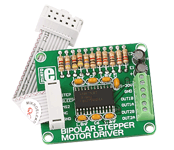
The Bipolar Stepper Motor Driver Board enables you to add stepper motor control to your applications. There is an on-board microstepping motor driver A3967SLB. The board supports Mixed, Fast and Slow Current-Decay Modes. |
|
|
|
 |

|
|
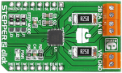
Stepper 2 click carries a A4988 microstepping motor driver along with screw terminals for connecting a motor and a required external power supply (minimum 7V). The output drive capacity of the motor is up to 35V and ±2A. The A4988 chip is designed to drive bipolar stepper motors in full-, half-, quarter-, eight-, and sixteenth-step modes. A set of three onboard jumpers (J1-J3) allow you to switch between the different stepping modes. The board communicates with the target MCU through EN, RST, SL, ST and DIR pins (corresponding to AN, RST, CS, PWM and INT pins of the default mikroBUS configuration). Stepper 2 click can use both a 3.3V and 5V power supply. |
|
|
|
 |

|
|
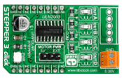
Stepper 3 click is a mikroBUS™ add-on board for driving unipolar stepper motors with precise controls (individual motor phases can be accessed separately).
The board carries a Texas Instruments ULN2003 High-Current Darlington transistor array for operating the motors.
Motors are connected through a 4-pin male connector on the top of the PCB. They can be driven by the click board's own power supply, or with an external power supply which can be brought through onboard screw terminals (up to 30V).
Stepper 3 click communicates with the target board MCU through mikroBUS™ PWM, AN, RST and CS pins (here used for individual motor phases, marked INA, INB, INC, IND).
The board is designed to use a 5V power supply only. |
|
|
|
 |
|

