|
|
| |
|
 | Search: |
|
|
|
|
|
 |

|
|
7x10 G click can be used for displaying letters on a display with 7x5 font resolution. It carries a matrix of 70 green LEDs driven by a pair of 8-bit serial-in, parallel-out shift registers, a Darlington Transistor array and a Johnson counter.
7x10 G click is designed to run on either 3.3V or 5V power supply. It communicates with the target microcontroller over SPI interface, with additional functionality provided by the following pins on the mikroBUS™ line: AN, PWM, RST. |
|
|
|
|
 |

|
|
8x8 R Click is an add-on board in the mikroBUS form factor. It's a compact and easy solution for adding an 8x8 LED matrix display to your design. It features the MAX7219 8-digit LED display driver module as well as 64 LED diodes. 8x8 Click communicates with the target microcontroller via four SPI lines (DIN, DOUT, CLK and CS). The board is designed to be powered by 5V, but can also communicate with 3.3V MCUs. |
|
|
|
 |

|
|
7x10 R click carries a matrix of 70 red LEDs driven by a pairs of 8-bit serial-in, parallel-out shift registers, a Darlington Transistor array and a Johnson counter. 7x5 is a standard resolution for displaying ASCII characters, so 7x10 click is essentially a dual-character display capable of showing letters in more readable typefaces compared to a 14-segment display. The click communicates with the target MCU through the mikroBUS SPI interface (SCK, SDO, SDI), with additional functionality provided by R CLK, MR#, LATCH and R RST pins. 7x10 R click is designed to use either a 3.3V or a 5V power supply. |
|
|
|
 |

|
|
16x9 G click contains a green LED matrix and the IS31FL3731 audio modulated matrix LED driver. The dimension of the LED matrix is 16x9. Each LED can be controlled individually – both for on/off control and light intensity. The click is designed to run on either 3.3V or 5V power supply. It communicates with the target microcontroller over I2C interface. |
|
|
|
 |

|
|
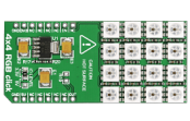
4x4 RGB click carries a matrix of 16 WS2812 RGB LEDs and a MCP1826 low dropout regulator. These LEDs actually consist of three single colored LEDs (Red, Green and Blue), plus a control chip in a single package; various colors can be reproduced by mixing the intensity of each LED. However, don't drive the LEDs to maximum brightness because it will generate excessive heat and draw more current that advisable (up to 0.7A) which could potentially damage the mainboard. Also, don't touch the board when it's in use. The LED matrix is connected to the target board microcontroller through the mikroBUS RST pin. The board uses either a 3.3V or 5V power supply. |
|
|
|
 |
|
|

