The integrated circuit labeled 74HC595 controls the bar graph display and it has a very wide application in electronics. After the 8-bit data is loaded into the internal registry of this chip through the SPI interface, the data is translated to the parallel 8-bit output by activating the STCP pin, thus controlling the display. Bar graph displays are often used to create various types of VU meters, status indicators, different types of counters and similar devices.
How does it work?
When it comes to driving an array of LED segments, using so-called shift-register ICs is almost unavoidable. This Click board™ uses a single 74HC595 IC, a tri-state, serial-in, parallel-out, 8-bit shift-register with output latch, from Texas Instruments. It is used to drive the SMA-B500LE a monochrome (red) 5 segment bar graph array, from American Opto Plus LED corporation. The 74HC595 ICs is comprised of a D-type internal storage register, and a serial-to-parallel shift register, both 8 bits wide. Each of these registers has its own clock line, making it possible to clock in the desired data in, and then clock it out to the parallel output pins when needed.

The SMA-B500LE bar graph LED array has 5 red LED segments. Each segment contains three LEDs, with their cathodes connected in a single point and routed out as the single common cathode pin. This results with a bar graph display that has only six pins, even though it uses 15 LED elements in total. Similarly, all the anodes of the LED segments are routed to a single pin, which is connected to the drain of the P channel MOSFET, while its source is connected to the VCC. Driving the gate of the MOSFET using the PWM pin of the mikroBUS™ allows dimming of the LED bar graph display, by changing the pulse width of the applied PWM signal.
The Click board™ communicates with the host MCU over the SPI interface, routed to the mikroBUS™ MOSI and SCK pins, labeled as SDI and SCK on this Click board™, respectively. Five bits of information are pushed through the serial data input pin (DS) of the 74HC595 IC, routed to the SDI pin. The construction of the SPI interface is such that it operates with 8-bit long words, so the whole data word needs to be clocked in before it is latched on the output. However, the values of the bits that correspond to the non-connected pins of the 74HC595 IC will be disregarded.
The Output Enable pin (#OE) is routed to the AN pin of the mikroBUS™, and it is labeled as OE. If this pin is at the HIGH logic level, the outputs Q0 to Q7S of the 74HC595 IC will be set at HIGH-Z (high impedance mode) meaning that they will become disconnected. Regardless of the logic state on other pins, the outputs will not change from this state, until #OE is brought down to a LOW logic level. Memory content and the logic states at the output pins will be unaffected, meaning that the OE can be used to turn the segments of the bar graph on or off without affecting their states (like a simple SPST switch in series with the LED segment of the bar graph)
After the data word has been clocked in, the master SPI clock should be stopped, and the CS pin should be driven to a HIGH logic level. The CS pin of the mikroBUS™ is routed to the STCP pin of the 74HC595 IC. A rising edge on the STCP input pin of the 74HC595 IC will latch the data from the internal storage register to the output pins, changing the states of its parallel output pins (Q0 to Q7). If a specific bit in the internal storage is 0, the state on the appropriate pin of the 74HC595 IC will become LOW. With their anodes connected to the positive voltage level already (provided that the P-type MOSFET is open), the segment will be lit. This means that the logical 0 lights up a segment, while 1 turns it off.
The #MR pin is used to clear the data in the internal storage register of the 74HC595 IC. The LOW logic level on this pin will clear the content of this storage register, but it will not turn off the outputs which are already activated. The #MR pin is routed to the RST pin of the mikroBUS™ and it is pulled to a HIGH logic level by the onboard resistor.
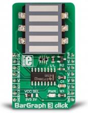
BarGraph 3 click can work with both 3.3V and 5V MCUs. The operating voltage selection can be done via the onboard SMD jumper, labeled as VCC SEL.
Specifications
| Type |
LED Segment |
| Applications |
It can be used for displaying of various signal or status properties, for building VU-meters, and various types of gauges and signal indicators |
| On-board modules |
74HC595, 8-bit serial-in, parallel-out shift registers with output latches, from Texas Instruments; SMA-B500LE, a monochrome (white) 5 segment bar graph array, from American Opto Plus LED corporation |
| Key Features |
Clean and bright five-segment LED bar graph, with uniform light distribution, simple to use with included software library functions. Controlled by the popular 74HC595 shift register IC, dimmable with the PWM signal applied over the mikroBUS™ PWM pin. |
| Interface |
GPIO,PWM,SPI |
| Input Voltage |
3.3V or 5V |
| Click board size |
M (42.9 x 25.4 mm) |
The Pinout diagram
This table shows how the pinout on BarGraph 3 Click corresponds to the pinout on the mikroBUS™ socket (the latter shown in the two middle columns).
| Notes |
Pin |
 |
Pin |
Notes |
|---|
| Output Enable |
OE |
1 |
AN |
PWM |
16 |
PWM |
PWM dimming |
| Data Clear |
RST |
2 |
RST |
INT |
15 |
INT |
|
| Latch IN |
CS |
3 |
CS |
RX |
14 |
NC |
|
| SPI Clock |
SCK |
4 |
SCK |
TX |
13 |
NC |
|
| |
NC |
5 |
MISO |
SCL |
12 |
NC |
|
| SPI IN |
SDI |
6 |
MOSI |
SDA |
11 |
NC |
|
| Power supply |
3V3 |
7 |
3.3V |
5V |
10 |
5V |
Power Supply |
| Ground |
GND |
8 |
GND |
GND |
9 |
GND |
Ground |
Onboard settings and indicators
| Label |
Name |
Default |
Description |
|---|
| PWR |
PWR |
- |
Power LED indicator |
| VCC SEL |
VCC SEL |
Left |
Power supply voltage selection: left position 3.3V, right position 5V |
Software support
We provide a library for the BarGraph 3 click on our LibStock page, as well as a demo application (example), developed using MikroElektronika compilers. The demo can run on all the main MikroElektronika development boards.
Library Description
The library initializes and defines SPI bus driver and drivers that offer a choice for writing data in registers and reading data from registers. The library includes functions for logging values on the BarGraph display. The user can enable and disable the chip with the function bargraph3_enable(), which is supported in the library.
Key functions:
void bargraph3_display(uint8_t ctrl, uint8_t dir, uint8_t counter) - Displays functionvoid bargraph3_enable(uint8_t state) - Functions for enabling the chip
Examples description
The application is composed of the three sections :
- System Initialization - Initializes SPI module and sets AN, RST, CS and PWM pin as OUTPUT
- Application Initialization - Initialization driver init, enable device and set PWM
- Application Task - (code snippet) - Counter passes through the loop and logs the value of the counter on the bar graph di
void applicationTask()
{
    uint8_t bargraph_cnt;

    for (bargraph_cnt = 0; bargraph_cnt <= 5; bargraph_cnt++)
    {
        bargraph3_display(_BARGRAPH3_INCREASE_LED, _BARGRAPH3_DIRECTION_BOTTOM_TO_TOP, bargraph_cnt);
        Delay_1sec();
    }

}
The full application code, and ready to use projects can be found on our LibStock page.
Other mikroE Libraries used in the example:
Additional notes and information
Depending on the development board you are using, you may need USB UART click, USB UART 2 click or RS232 click to connect to your PC, for development systems with no UART to USB interface available on the board. The terminal available in all MikroElektronika compilers, or any other terminal application of your choice, can be used to read the message.
mikroSDK
This click board is supported with mikroSDK - MikroElektronika Software Development Kit. To ensure proper operation of mikroSDK compliant click board demo applications, mikroSDK should be downloaded from the LibStock and installed for the compiler you are using.
For more information about mikroSDK, visit the official page.