Having the ability to adjust the voltage on the AN pin very accurately, this Click board™ can be used for development of applications that require voltage reference other than what is commonly available as an output from a dedicated IC. This includes HMI applications where the potentiometer can be used to provide fine control the movement of a step motor, or intensity of a LED segment, backlight amount of a TFT screen, and similar applications that require fine control of the voltage reference.
How does it work?
This Click board™ uses a very simple design: the MCP1541, a precision voltage reference IC from Microchip is used to provide the voltage of 4.096V. is fed to an input of an operational amplifier, that acts as the buffer, with the unity gain. The output of the first buffer is fed to one end of a high-precision trimmer-potentiometer. The second end of the potentiometer is grounded, while the middle tap of the potentiometer is used as the input to a second buffer. The output of the second buffer is routed to the AN pin of the mikroBUS™, allowing the host microcontroller (MCU) to use the output voltage for any purpose.
.jpg)
The design uses the MCP6022, a dual, rail-to-rail operational amplifier from Microchip. This operational amplifier is a perfect choice for this design, as it allows rail-to-rail operation, uses a single power supply of 5V, and has a stable unity gain. Without the buffers, the variable impedance would affect the reference voltage. The reference voltage IC can provide less than 10 mA, with the significant voltage drop for output currents exceeding 2 mA. Therefore, the MCP6022 used as a dual buffer ensures good stability of the circuit.
The potentiometer itself is a multi-turn type of potentiometer which provides high accuracy. It is equipped with a screw, which can be rotated 20 times between the end positions. This allows the resistance to be precisely selected. The fact that the screw fits tightly into the casing of the potentiometer, ensures that no resistance variations are possible, unlike the conventional knob or slider potentiometers.
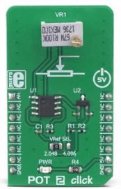
POT 2 click is equipped with the SMD jumper, which is used to select the voltage reference for the potentiometer. There are two options available: 2.048V and 4.096V. These values are the most commonly used voltage references for different kinds of A/D converters. Most MCUs which use 3.3V for the power supply, do not have the option to use 4.096V (full voltage output of the MCP1541 IC), so an option to select 2.048V by dividing the output voltage of the MCP1541 IC, is very useful in that case. The voltage reference can be selected by moving the SMD jumper labeled as VRef SEL to the desired position (2.048V or 4.096V).
Specifications
| Type |
Measurements |
| Applications |
It can be used for development of different types of HMI applications where the potentiometer can be used to provide fine control the movement or to change the intensity of a LED segment in fine steps, backlight amount of a TFT screen, etc. |
| On-board modules |
MCP1541, a precision voltage reference IC; MCP6022, a dual, rail-to-rail operational amplifier, both from Microchip |
| Key Features |
High precision, 20 turns trimmer potentiometer, buffered reference voltage output, selectable maximum value for the adjustable voltage reference |
| Interface |
Analog |
| Input Voltage |
5V |
| Click board size |
M (42.9 x 25.4 mm) |
Pinout diagram
This table shows how the pinout on POT 2 Click corresponds to the pinout on the mikroBUS™ socket (the latter shown in the two middle columns).
| Notes |
Pin |
 |
Pin |
Notes |
|---|
| Ref. Voltage OUT |
AC |
1 |
AN |
PWM |
16 |
NC |
|
| |
NC |
2 |
RST |
INT |
15 |
NC |
|
| |
NC |
3 |
CS |
RX |
14 |
NC |
|
| |
NC |
4 |
SCK |
TX |
13 |
NC |
|
| |
NC |
5 |
MISO |
SCL |
12 |
NC |
|
| |
NC |
6 |
MOSI |
SDA |
11 |
NC |
|
| |
NC |
7 |
3.3V |
5V |
10 |
+5V |
Power Supply |
| Ground |
GND |
8 |
GND |
GND |
9 |
GND |
Ground |
Onboard settings and indicators
| Label |
Name |
Default |
Description |
|---|
| LD1 |
PWR |
- |
Power LED indicator |
| JP1 |
VRef SEL |
Left |
Reference voltage level selection: left position 2.048V, right position 4.096V |
Software support
We provide a library for the POT 2 Click on our LibStock page, as well as a demo application (example), developed using MikroElektronika compilers. The demo can run on all the main MikroElektronika development boards.
Library Description
The library contains the functions needed to start and read the ADC values.
Key functions:
void pot2_adcInit() - ADC Init function.void pot2_adcSetInputChannel() - ADC set input channel function.uint32_t pot2_adcRead() - ADC read function.
Examples description
The application is composed of the three sections :
- System Initialization - Initializes LOG to print data that is read from ADC.
- Application Initialization - Initialization ADC Init and sets ADC input channel.
- Application Task - (code snippet) - Reads data from ADC and logs data to USBUART every 500 ms.
void applicationTask()
{
    uint16_t ADC_value;
    char demoText[ 50 ];

    ADC_value = pot2_adcRead();

    WordToHex(ADC_value, demoText);
    mikrobus_logWrite(" ADC value: 0x", _LOG_TEXT);
    mikrobus_logWrite(demoText, _LOG_LINE);
    Delay_ms( 500 );
}
The full application code, and ready to use projects can be found on our LibStock page.
Other mikroE Libraries used in the example:
Additional notes and informations
Depending on the development board you are using, you may need USB UART click, USB UART 2 click or RS232 click to connect to your PC, for development systems with no UART to USB interface available on the board. The terminal available in all MikroElektronika compilers, or any other terminal application of your choice, can be used to read the message.