The ACS723 has a precisely trimmed analog output, which changes linearly with the applied current. Its accuracy is further optimized through the Allegro's patented digital temperature compensation. Its excellent galvanic isolation simplifies the application, allowing the Click board™ to be connected directly to the high side of the measured circuit. It can be used to measure both DC and AC current. The ACS723 IC features a bandwidth selection pin, used to adjust the measurement to a frequency bandwidth of the application. Hall Current 6 click can be used in motor control applications, load detection and management applications, switch-mode power supplies, overcurrent fault protection applications, and similar applications that require accurate and reliable current sensing.
 DO NOT TOUCH THE BOARD WHILE THE EXTERNAL POWER SUPPLY IS ON!
Note: The Click board™ is to be used by trained personnel only, while applying high voltages. A special care should be taken when working with hazardous voltage levels.
How does it work?
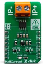
Hall Current 6 utilizes the ACS723(LLCTR-05AB-T), a high-accuracy, galvanically isolated current sensor IC, from Allegro Microsystems. This sensor utilizes the Hall effect phenomenon to measure the current passing through the internally fused input pins of the IC. This allows the series resistance to stay very low. Current through the input rails of the IC generates a magnetic field, causing the Hall effect on the current through the integrated sensor. These two current circuits are completely isolated, with the basic isolation working voltage of about 297VRMS, allowing the Click board™ to be used in high-side current sensing applications.
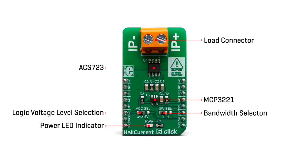
The output voltage changes linearly with the current in the primary circuit, with the ratio of 400mV/A, and it is fed to the MCP3221, a 12-bit analog to digital converter (ADC) with I2C interface, from Microchip. This is a well-established converter used in many Click board™ designs, thanks to its proven reliability, reasonably good sampling rate well suited for instrumentation applications (22.3 ksps), and simplicity of use. It converts the output voltage from the ACS723 into a digital value, which is available over the I2C interface. The output voltage of the ACS723 has a very linear dependency of the current through the primary pins, due to the Allegro's patented digital temperature compensation. Although it can be used in a rather limited current range of ±5A, it has a great accuracy of ±3% (referred to as a Total Output Error in the datasheet).
The ACS723 IC features a bandwidth selection pin, which allows the bandwidth selection according to the application it is used in. For example, when measuring current in some applications that operate at lower frequencies, limiting the bandwidth improves the noise performance, enabling to obtain results with higher accuracy. The bandwidth selection pin acts as a filter on the measurement line, allowing two cutoff frequencies: 20kHz and 80kHz. The BW_SEL pin of the ACS723 is routed to the small SMD jumper, labeled as BW SEL. When the jumper is at the position 0, the bandwidth of the device is 80kHz.
The secondary side of the ACS733 is powered from the 5V mikroBUS™ rail. As explained earlier, current flowing through the primary conductors is galvanically isolated from the rest of the IC, protecting low-voltage parts of the Click board™, as well as the host MCU. The Click board™ should be connected in series with the load through which the current is measured, by using the load connector, labeled with IP+ and IP-. A very low internal resistance of only 0.65 m? across the primary conductors, will not disturb the current through the circuit, so the Click board™ will not introduce its own error into the measurement, thus acting as a nearly-perfect ammeter.
The voltage at which the I2C lines are pulled up can be selected using the VCC SEL jumper. The ability to select the logic voltage level allows this Click board™ to be interfaced with a wide range of different MCUs, operating at both 3.3V and 5V.
Specifications
| Type |
Current |
| Applications |
It can be used in motor control applications, load detection and management applications, switch-mode power supplies, overcurrent fault protection applications, etc. |
| On-board modules |
ACS723, a high-accuracy, galvanically isolated current sensor IC, from Allegro Microsystems; MCP3221, a 12-bit analog to digital converter (ADC) with I2C interface, from Microchip. |
| Key Features |
Very low series resistance, which makes this sensor an ideal ammeter, wide current range, factory calibrated accuracy, low count of external components, high isolation voltage, added ADC for simpler interfacing to embedded systems. |
| Interface |
I2C |
| Input Voltage |
3.3V,5V |
| Click board size |
M (42.9 x 25.4 mm) |
Pinout diagram
This table shows how the pinout on Hall Current 6 click corresponds to the pinout on the mikroBUS™ socket (the latter shown in the two middle columns).
| Notes |
Pin |
 |
Pin |
Notes |
|---|
| |
NC |
1 |
AN |
PWM |
16 |
NC |
|
| |
NC |
2 |
RST |
INT |
15 |
NC |
|
| |
NC |
3 |
CS |
RX |
14 |
NC |
|
| |
NC |
4 |
SCK |
TX |
13 |
NC |
|
| |
NC |
5 |
MISO |
SCL |
12 |
SCL |
I2C Clock |
| |
NC |
6 |
MOSI |
SDA |
11 |
SDA |
I2C Data |
| Power Supply |
3.3V |
7 |
3.3V |
5V |
10 |
5V |
Power Supply |
| Ground |
GND |
8 |
GND |
GND |
9 |
GND |
Ground |
Hall Current 6 Click electrical specifications
| Description |
Min |
Typ |
Max |
Unit |
|---|
| Primary conductor resistance |
- |
0.65 |
- |
m? |
| Measurement range with optimized accuracy |
-5 |
- |
+5 |
A |
| Sensitivity |
- |
400 |
- |
mV/A |
| Working voltage for basic isolation |
- |
- |
297 |
V(RMS) |
Onboard settings and indicators
| Label |
Name |
Default |
Description |
|---|
| PWR |
PWR |
- |
Power LED indicator |
| VCC SEL |
VCC SEL |
Left |
Logic voltage level selection: left position 3.3V, right position 5V |
| BW SEL |
BW SEL |
Left |
Bandwidth selection: left position 80kHz (0), right position 20kHz (1) |
Software support
We provide a library for the Hall Current 6 click on our LibStock page, as well as a demo application (example), developed using MikroElektronika compilers. The demo can run on all the main MikroElektronika development boards.
Library Description
This library provides basic functionality for reading the current value and controlling the click board.
Key functions:
float hallcurrent6_getCurrent() - Reads Current data in mA.uint16_t hallcurrent6_readData() - Reads ADC current data.
Examples description
The application is composed of the three sections :
- System Initialization - Initializes I2C module.
- Application Initialization - Initializations driver init.
- Application Task - Reads Current data in mA and logs this data to USBUART every 1 sec.
void applicationTask()
{
    char demoText[ 50 ];
    float Current;

    Current = hallcurrent6_getCurrent();

    mikrobus_logWrite(" Current value: ", _LOG_TEXT);
    FloatToStr(Current, demoText);
    mikrobus_logWrite(demoText, _LOG_TEXT);
    mikrobus_logWrite(" mA", _LOG_LINE);

    mikrobus_logWrite(" ------------------------- ", _LOG_LINE );
    Delay_ms( 1000 );
}
The full application code, and ready to use projects can be found on our LibStock page.
Other mikroE Libraries used in the example:
Additional notes and informations
Depending on the development board you are using, you may need USB UART click, USB UART 2 click or RS232 click to connect to your PC, for development systems with no UART to USB interface available on the board. The terminal available in all MikroElektronika compilers, or any other terminal application of your choice, can be used to read the message.
mikroSDK
This click board is supported with mikroSDK - MikroElektronika Software Development Kit. To ensure proper operation of mikroSDK compliant click board demo applications, mikroSDK should be downloaded from the LibStock and installed for the compiler you are using.
For more information about mikroSDK, visit the official page.