How does it work?
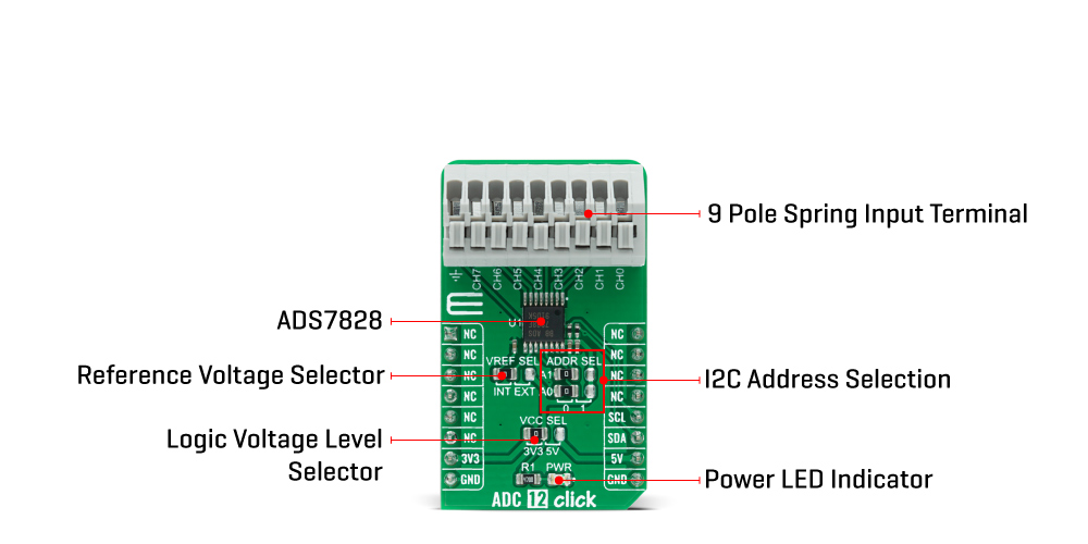
ADC 12 Click is based on the ADS7828, a low-power 12-bit data acquisition device that features a serial I2C interface and an 8-channel multiplexer from Texas Instruments. The architecture of the ADS7828, which is a classic Successive Approximation Register (SAR) A/D converter, is based on capacitive redistribution that inherently includes a sample-and-hold function. It has an integrated I2C input and output port as well as screw terminal connectors for each analog input channel. It is controlled by an internally generated free-running clock. When the ADS7828 is not performing conversions or being addressed, it keeps the A/D converter core powered off, and the internal clock does not operate.
When the A/D converter enters the Hold mode, the voltage on the selected channel pin of the input terminal is captured on the internal capacitor array. The input current on the analog inputs depends on the conversion rate of the device. During the sample period, the source must charge the internal sampling capacitor. After the capacitor has been fully charged, there is no further input current. The amount of charge transfer from the analog source to the converter is a function of conversion rate.
ADC 12 Click communicates with MCU using the standard I2C 2-Wire interface with a frequency up to 100kHz in the Standard, up to 400kHz in the Fast, and up to 3.4MHz in the High-Speed mode. It also allows the choice of the last two least significant bits (LSB) A0 and A1 by positioning SMD jumpers labeled as ADDR SEL to an appropriate position marked as 0 and 1. This Click board™ also posses a jumper for selecting the reference voltage labeled as VREF SEL. The ADS7828 can operate with an internal 2.5V reference or an external reference (in this case logic voltage level VCC), which can be selected by positioning SMD jumpers to an appropriate position marked as INT and EXT.
This Click board™ is designed to be operated with both 3.3V and 5V logic voltage levels that can be selected via VCC SEL jumper. This allows for both 3.3V and 5V capable MCUs to use the I2C communication lines properly. However, the Click board™ comes equipped with a library that contains easy to use functions and an example code that can be used as a reference for further development.
Specifications
| Type |
ADC |
| Applications |
Can be used for applications requiring the A/D converter to be close to the input source in remote locations and for applications requiring isolation. |
| On-board modules |
ADC 12 Click is based on the ADS7828, a low-power 12-bit data acquisition device that features a serial I2C interface and an 8-channel multiplexer from Texas Instruments. |
| Key Features |
Low power consumption, 12-bit data acquisition device, 8-channel multiplexer, internal voltage reference, and more. |
| Interface |
I2C |
| ClickID |
No |
| Compatibility |
mikroBUS |
| Click board size |
M (42.9 x 25.4 mm) |
| Input Voltage |
3.3V or 5V |
Pinout diagram
This table shows how the pinout on ADC 12 Click corresponds to the pinout on the mikroBUS™ socket (the latter shown in the two middle columns).
| Notes |
Pin |
 |
Pin |
Notes |
|---|
| |
NC |
1 |
AN |
PWM |
16 |
NC |
|
| |
NC |
2 |
RST |
INT |
15 |
NC |
|
| |
NC |
3 |
CS |
RX |
14 |
NC |
|
| |
NC |
4 |
SCK |
TX |
13 |
NC |
|
| |
NC |
5 |
MISO |
SCL |
12 |
SCL |
I2C Clock |
| |
NC |
6 |
MOSI |
SDA |
11 |
SDA |
I2C Data |
| Power Supply |
3.3V |
7 |
3.3V |
5V |
10 |
5V |
Power Supply |
| Ground |
GND |
8 |
GND |
GND |
9 |
GND |
Ground |
Onboard settings and indicators
| Label |
Name |
Default |
Description |
|---|
| LD1 |
PWR |
- |
Power LED Indicator |
| JP1 |
VCC SEL |
Left |
Power Supply Voltage Selection 3V3/5V: Left position 3V3, Right position 5V |
| JP2 |
VREF SEL |
Left |
Reference Voltage Selection INT/EXT: Left position INT, Right position EXT |
| JP3-JP4 |
ADDR SEL |
Left |
I2C Address Selection: Left position 0, Right position 1 |
ADC 12 Click electrical specifications
| Description |
Min |
Typ |
Max |
Unit |
|---|
| VCC Supply Voltage |
-0.3 |
- |
6 |
V |
| ADC Supply Voltage |
0 |
- |
5.25 |
A |
| Power Consumption |
- |
- |
0.68 |
mW |
| Operating Temperature Range |
-40 |
- |
+85 |
°C |
Software Support
We provide a library for the ADC 12 Click on our LibStock page, as well as a demo application (example), developed using MikroElektronika compilers. The demo can run on all the main MikroElektronika development boards.
Library Description
The library covers all the necessary functions to control ADC 12 Click board™. User can set or read input mode or power-down mode, read raw adc or voltage and send command to input register or read output.
Key functions:
void adc12_send_cmd ( uint8_t cmd_byte ); - Function is used to configure the device.uint16_t adc12_single_ended ( uint8_t chan, uint16_t v_ref ); - Function is used to get raw ADC value.uint16_t adc12_differential ( uint8_t chan, uint16_t v_ref ); - Function is used to get raw ADC value.
Examples description
The application is composed of three sections :
- System Initialization - Initializes I2C and LOG structures, and start to write log.
- Application Initialization - Initalizes I2C driver and configures ADC 12 Click board™, enables single-ended inputs, and turns on Internal Reference and ADC.
- Application Task - This is an example that shows the capabilities of the ADC 12 Click by reading raw value and voltage inputed on channel 0 and displaying data every second.
void application_task ( )
{
    mikrobus_logWrite( "Read Channel 0 raw", _LOG_LINE );
    adc_r = adc12_single_ended ( ADC12_SNGL_END_CH0, ADC12_INT_V_REF_VAL );
    WordToStr( adc_r, log_txt );
    Ltrim( log_txt );
    mikrobus_logWrite( "ADC raw: ", _LOG_TEXT );
    mikrobus_logWrite( log_txt, _LOG_LINE );
    mikrobus_logWrite( "", _LOG_LINE );
    mikrobus_logWrite( "Read Channel 0 voltage", _LOG_LINE );
    adc_v = adc12_single_ended_volt ( ADC12_SNGL_END_CH0, ADC12_INT_V_REF_VAL );
    FloatToStr( adc_v, log_txt );
    Ltrim( log_txt );
    mikrobus_logWrite( "ADC raw: ", _LOG_TEXT );
    mikrobus_logWrite( log_txt, _LOG_TEXT );
    mikrobus_logWrite( "mV", _LOG_LINE );
    mikrobus_logWrite( "------------------------", _LOG_LINE );
    Delay_ms( 1000 );
}
The full application code, and ready to use projects can be found on our LibStock page.
Other mikroE Libraries used in the example:
Additional notes and informations
Depending on the development board you are using, you may need USB UART click, USB UART 2 click or RS232 click to connect to your PC, for development systems with no UART to USB interface available on the board. The terminal available in all MikroElektronika compilers, or any other terminal application of your choice, can be used to read the message.
mikroSDK
This Click board™ is supported with mikroSDK - MikroElektronika Software Development Kit. To ensure proper operation of mikroSDK compliant Click board™ demo applications, mikroSDK should be downloaded from the LibStock and installed for the compiler you are using.
For more information about mikroSDK, visit the official page.
Resources
Downloads