|
|
| |
|
 | Search: |
|
|
|
|
|
 |
|
|
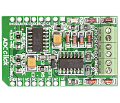
ADC Click is an accessory board in mikroBus form factor. It includes a 12-bit Analog-to-Digital Converter (ADC) MCP3204 that features 50k samples/second, 4 input channels and low-power consumption (500nA typical standby, 2uA max). Board uses industry standard SPI communication interface. It is small in size and features convenient screw terminals for easier connections. Board is set to use 3.3V power supply by default. Place PWR SEL SMD jumper to 5V position if used with 5V systems. |
|
|
|
|
 |
|
|
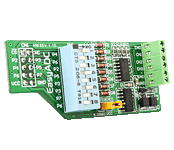
The EasyADC Board enables you to connect your development board to a 12-bit analog-to-digital converter (ADC). The board features a 12-bit analog-to-digital converter (ADC) MCP3204 with 4 inputs and 4.096 voltage reference. |
|
|
|
 |
|
|
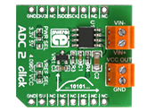
ADC 2 click carries MCP3551/3, which is a 22-bit ADC with automatic internal offset and gain calibration. This high precision analog-to-digital converter has total unadjusted error of less than 10 ppm, and low-output noise of 2.5 µV RMS. The board carries two pairs of screw screw terminals: VIN- for bringing in reference voltage, VIN+ for the positive voltage. VCC out and GND are output voltages. The click communicates with the target board through mikroBUS CS, CSK and MISO lines. Can use either a 3.3V or 5V power supply. |
|
|
|
 |
|
|
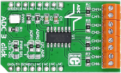
ADC3 click carries Microchip's MCP3428 16-bit multichannel analog-to-digital converter. The click has four pairs of screw terminals onboard, letting you access the chip's four differential input channels. At the highest resolution of 16-bits, the chip outputs conversion results at 15 samples per second. At 14-bits, the sample rate is 60 SPS. Maximum conversion speed is achieved in 12-bit mode, 240 samples per second. A pair of onboard jumpers allow switching between different I2C addresses. ADC3 click communicates with the target MCU through mikroBUS I2C pins (SCL, SDA). It is designed to use either a 3.3V or 5V power supply. |
|
|
|
 |
|
|
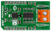
Voltmeter click is a mikroBUS add-on board for measuring voltage in an external electric circuit.
The board is designed to measure Direct Current only, and has a measurement range from 0 to 24V (it's possible to measure both positive and negative charges).
The design of the board is based on an OpAmp set up as a differential amplifier with a buffered input.
Two onboard screw terminals (probe+ and probe-) are bringing in the current, which then flows through a row of four resistors. A voltage – proportional to the input charge – is generated across the last two resistors. From there it is sent to the differential amplifier that further intensifies the difference between the two inputs (+/-).
The resulting charge is exactly 33 times lower than the actual measured voltage. It is converted by an onboard 12-bit ADC before being outputted through the mikroBUS SPI interface (the firmware in the target board MCU should be set up to multiply the ADC value to get the actual voltage). It is also possible to output the analog value directly through the mikroBUS AN pin (useful if the target MCU has a higher resolution ADC).
The board can work with either a 3.3V or a 5V power supply. |
|
|
|
 |
|
|

