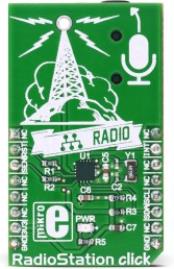
RadioStation click is a unique click board™ that can be used to broadcast the music via the FM radio band. It features the Si4713-B30 from Silicon Labs, the best in class integrated FM broadcast stereo transmitter, which operates in the frequency range of 76MHz to 108MHz. It can also broadcast RDS/RDBS data. The click board™ can be equipped with a small FM antenna, which is used to extend the broadcasting range.
One of the advantages of this versatile FM broadcast stereo transmitter IC is that it needs almost no external components so it is very easy to work with it. That makes it an ideal solution for using it in cellular phones, MP3 players, portable media players, wireless speakers, personal computers and any other applications, where short-range radio broadcasting is wanted.
How does it work?
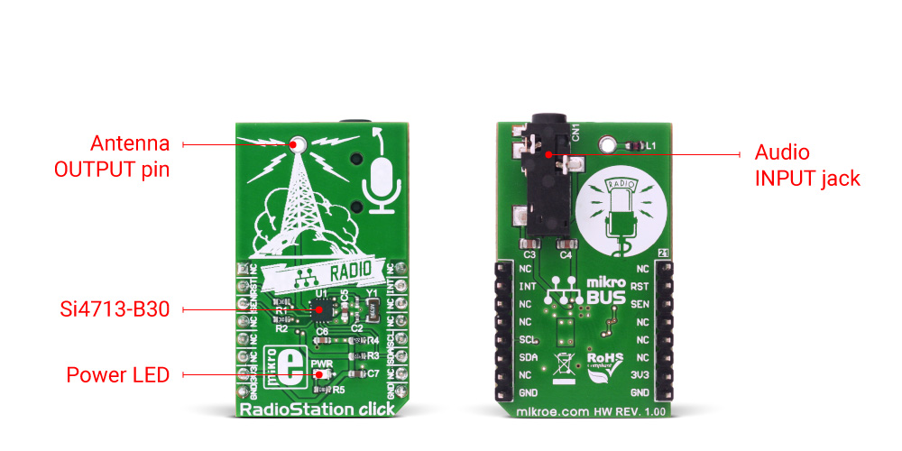
The RadioStation click broadcasts the audio signal by utilizing principles of the FM radio broadcasting. The audio signal, brought to the low noise analog input terminals of the Si4713-B30 routed to a mini 3.5 female jack on board, is attenuated and converted into an alias free, digital format. The digitalized audio is then sent to the digital signal processor (DSP) section of the Si4713-B30 IC. This input is suited for line-level signals, up to 636mVpp.
The Si4713-B30 IC performs the frequency modulation in the digital domain, in order to achieve high fidelity and optimal performance. The onboard DSP provides modulation adjustment and audio dynamic range control of the signal, for the best listening experience. Audio signal is processed to have the optimal dynamic qualities. Also, Si4713 has a programmable low audio and high audio level indicators that allow enabling and disabling of the carrier signal, based on the presence of an audio content.
The integrated DSP also takes care of the stereo MPX encoding and FM modulation of the signal. The low level digital intermediate frequency (IF) signal is then filtered out and sent to the output stage mixer, where it is converted to a radio frequency signal (RF). RF harmonics and noise get filtered out additionally, to get a signal which is compliant with local regulations on RF transmission (FCC, ETSI, ARIB…). The RF signal is broadcasted via the small antenna. The device supports all kinds of closed loop/pole FM antennas.
The click is designed for communication over the I2C/2-wire control interface. When selecting 2-wire mode, SCLK pin should stay at a HIGH logic level during the rising edge on the RST pin, and stay HIGH until after the first start condition. Also, a start condition must not occur within 300nS before the rising edge on the RST pin. The 2-wire bus mode uses only the SCL and SDA pins for communication.
The INT# pin of the Si4713-B30 is routed to the INT pin on the mikroBUS™ and it can be used to provide an interrupt.
The SEN# pin of the Si4713-B30 is routed to the CS pin on the mikroBUS™ and it is used for selecting the I2C address:
when SEN# is set to a HIGH logic level, the 7bit I2C address will be 1100011.
when SEN# is set to a LOW logic level, the 7bit I2C address will be 0010001.
The RST# pin of the of the Si4713-B30 is routed to the RST pin on the mikroBUS™. Setting it to a LOW logic state will disable analog and digital circuitry, reset the registers to their default settings, and disable the bus. Setting the RST pin to a HIGH logic level will bring the device out of reset and place it in power down mode. A power down mode is available to reduce power consumption when the part is idle. Putting the device in power down mode will disable analog and digital circuitry and keep the bus active.
The Si4713-B30 IC has the capability of the received signal measurement. The antenna which is used to broadcast the signal can also be used to accept the incoming signal, sent by the receiving device. Although it can be used both to receive and transmit signal, the antenna can't operate in both modes simultaneously. This feature can be useful when calibrating the transmission power of the click board.
Note: The Si4713-B30 integrates the complete transmit functions for standards-compliant unlicensed FM broadcast stereo transmission. The user application must comply with the local regulations on radio frequency (RF) transmission.
Specifications
Type
FM
Applications
Cellular phones, MP3 players, portable media players, wireless speakers, personal computers and any other applications, where audio broadcasting on the small distance is required.
On-board modules
Si4713-B30 from Silicon Labs, the best in class integrated FM broadcast stereo transmitter
Key Features
Easy to set, high quality integrated FM radio transmitter. It uses advanced audio processing techniques to avoid over-modulation and to achieve perfect levels of audio for broadcasting.
Interface
I2C
Input Voltage
3.3V
Click board size
M (42.9 x 25.4 mm)
Pinout diagram
This table shows how the pinout on RadioStationclick corresponds to the pinout on the mikroBUS™ socket (the latter shown in the two middle columns).
Notes
Pin
Pin
Notes
NC
1
AN
PWM
16
NC
Device reset
RST
2
RST
INT
15
INT
GPO /Interrupt
I2C address selection
SEN
3
CS
RX
14
NC
NC
4
SCK
TX
13
NC
NC
5
MISO
SCL
12
SCL
I2C clock
NC
6
MOSI
SDA
11
SDA
I2C data
Power supply
3V3
7
3.3V
5V
10
NC
Ground
GND
8
GND
GND
9
GND
Ground
RadioStation click electrical specifications
Description
Min
Typ
Max
Unit
Ambient temperature
-20
85
°C
Broadcasting frequency range
76
108
MHz
Transmit emissions in-band (76–108 MHz)
-30
dBc
SNR
53
58
dB
THD
0.5
%
Additional pins
Name
I/O
Description
ANT
O
ANTENNA output pin
Onboard settings and indicators
Label
Name
Default
Description
PWR
Power LED
-
Power LED indicator
Software support
We provide a library for the RadioStation click on our LibStock page, as well as a demo application (example), developed using MikroElektronika compilers. The demo can run on all the main MikroElektronika development boards.
Library Description
The RadioStation click board™ communicates with the controller by using the I2C/2-wire interface. The library contains a wide set of functions for the complete control over the RadioStation click. Some of the functions also return the status, so it is possible to take an action in the case of error.
uint8_t RADIOSTATION_SetTuneFrequency(uint16_t freq)- Sets tune frequency
uint8_t RADIOSTATION_SetTunePower(uint8_t voltage, uint8_t capacitance)- Sets tune power
Demo application shows how to configure RadioStation click to receive the signal from the audio connector and broadcast it on 100.00 MHz frequency.
The application is composed of three sections:
System initialization - Initializes GPIO pins, I2C peripheral used for communication between RadioStation click and MCU, and UART used for logging. This function also initializes driver.
Application initialization - (Code snippet) Powers on RadioStation click and setups frequency for signal emission and writes a message to UART when emission is started.
Application task - Sequentially reads measurements of the signal quality.
The full application code and ready to use projects can be found on our LibStock page.
Other mikroE Libraries used in the example:
UART
Additional notes and information
Depending on the development board you are using, you may need USB UART click, USB UART 2 click or RS232 click to connect to your PC, for development systems with no UART to USB interface available on the board. The terminal available in all MikroElektronika compilers, or any other terminal application of your choice, can be used to read the message.