This Click board™ is configured to drive a single speaker, using its outputs tied in parallel. It requires an external Power Supply Unit (PSU) for its operation. It can use a wide range of power supply voltages, from 3.5V up to 14.4V. Audio Amp 6 click is designed to be used along with the Audio Amp 5 click, for building home theater 2.1, 4.1, 5.1 or 7.1 systems. It is a perfect solution for the development of battery-powered Bluetooth® and wireless speakers, TV sets and PC monitors, and other types of consumer audio equipment applications. Due to its high efficiency, it can even be used as a sound reinforcement solution for various IoT applications.
How does it work?
The main component of Audio Amp 6 click is the TPA3138D2, a stereo class-D audio amplifier, from Texas Instruments. It has many features which make this IC a very attractive solution for battery-powered and stand-alone active speakers. It is very flexible regarding the PSU voltage: it can work with voltages within the range from 3.5V to 14.4V. With only 3.5V at the PSU connector, it can still deliver 1W of power to the 6? load (per channel). However, its nominal operating voltage is 12V, reaching up to 18.5W of power to the single connected 4? speaker, with 10% of Total Harmonic Distortion (THD).

The TPA3138D2 IC features a set of protections, including output short circuit, over-temperature, under-voltage, and over-voltage protection. If any of these protections are activated, they will be reported at the SD/FAULT (EN) I/O pin. The TPA3138D2 IC can also detect a constant DC current at the output. When a DC detection event occurs, the outputs are turned OFF, protecting the connected speakers that way. Very often, a DC detection event can be triggered when the circuit is powered up, so it is advisable to hold the EN pin to a LOW logic level for a short period, preventing faulty DC detection reports, as well as loud pops.
The output stage of the TPA3138D2 operates in Bridge-Tied Load (BTL) topology. This means that there are two outputs per channel: one inverted and one non-inverted (OUTN and OUTP). In the case of the Audio Amp 6 click, both of these differential outputs are tied in a bridge topology (PBTL), yielding even more power on a single speaker, at the cost of somewhat higher THD, which is still acceptable tradeoff in subwoofer/central speaker applications. The amplifier does not process the input in any way, therefore it should be connected to a pre-processed sound output from the active crossover or a dedicated SW/Center output from the audio playback device.
The class-d amplifier produces the sound by modulating the pulse-with of the output voltage. It offers a choice of two PWM modulation schemes, selectable by the MODE_SEL pin of the IC. This pin is routed to the mikroBUS™ RST pin, labeled as MDS on this Click board™. By default, MDS pin is pulled to a HIGH logic level by a resistor.
When the MDS pin is set to a LOW logic level, the TPA3138D2 uses the BD Modulation scheme. This modulation scheme is less power-efficient, but it yields better THD ratio. When set to a HIGH logic level, TPA3138D2 will operate using the 1SPW Modulation scheme, which is set for this Click board™ by default (pull-up resistor). This modulation scheme allows for very low idle current and better overall efficiency, at the expense of somewhat increased THD.
The SD/FAULT pin allows the host MCU to enable/disable outputs. By pulling this pin to a LOW logic level, the outputs are muted and the TPA3138D2 IC enters the low-current state, reducing the supply current to the absolute minimum level. Muting the TPA3138D2 before cutting down the power supply reduces pops and clicks that might appear in this case. The SD/FAULT pin is routed to the mikroBUS™ CS pin labeled as EN on this Click board™, and it is pulled to a HIGH logic level by a resistor.
There is a selectable input gain on Audio Amp 5 click. By applying a LOW logic level to the GAIN_SEL pin, the input gain is set to 20dB. A HIGH logic level sets the input gain to 26dB. This allows matching the input signal so that the optimal output level can be reached. This pin is routed to the mikroBUS™ PWM pin labeled as GS, and it is pulled to the LOW logic level by a resistor.
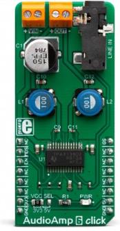
The external PSU should be connected to the VIN terminal. A line-level audio source can be connected to the LINE IN 3.5mm jack stereo connector, while the speaker should be connected to the OUT terminal. These terminals have their polarities marked on the top overlay.
Although the TPA3138D2 IC requires an external PSU, it still uses power from the mikroBUS™ for the logic levels of its control pins. There is a logic voltage level selection SMD jumper labeled as VCC SEL, which allows interfacing with both 3.3V and 5V-tolerant pins of the host MCU.
Specifications
| Type |
Amplifier |
| Applications |
This Click board™ is designed to be used along with the Audio Amp 5 click, for building home theater 2.1, 4.1, 5.1 or 7.1 systems. It is a perfect solution for the development of battery-powered Bluetooth® and wireless speakers, TV sets and PC monitors, and other types of consumer audio equipment applications. |
| On-board modules |
TPA3138D2, a stereo class-D audio amplifier, from Texas Instruments. |
| Key Features |
High efficiency, low power dissipation with no extra heat-sinks required, a set of protection features for reliable operation, it can be operated with the wide range of voltages, etc. |
| Interface |
GPIO |
| Input Voltage |
3.3V or 5V |
| Click board size |
L (57.15 x 25.4 mm) |
Pinout diagram
This table shows how the pinout on AudioAmp 6 click corresponds to the pinout on the mikroBUS™ socket (the latter shown in the two middle columns).
| Notes |
Pin |
 |
Pin |
Notes |
|---|
| |
NC |
1 |
AN |
PWM |
16 |
GS |
Gain Select |
| Mode Selection |
MDS |
2 |
RST |
INT |
15 |
NC |
|
| Chip Enable/Fault |
EN |
3 |
CS |
RX |
14 |
NC |
|
| |
NC |
4 |
SCK |
TX |
13 |
NC |
|
| |
NC |
5 |
MISO |
SCL |
12 |
NC |
|
| |
NC |
6 |
MOSI |
SDA |
11 |
NC |
|
| Power Supply |
3V3 |
7 |
3.3V |
5V |
10 |
5V |
Power Supply |
| Ground |
GND |
8 |
GND |
GND |
9 |
GND |
Ground |
AudioAmp 6 click electrical specifications
| Description |
Min |
Typ |
Max |
Unit |
|---|
| External PSU Voltage |
3.5 |
- |
14.4 |
V |
| Minimum load Impedance |
3.2 |
- |
- |
? |
| Continuous output power |
- |
18.5 |
- |
W |
| Total Harmonic Distortion (THD) at 18.5W; 4?; 12V |
- |
10 |
- |
% |
| Signal-to-Noise Ratio (SNR) |
- |
102 |
- |
dB |
Onboard settings and indicators
| Label |
Name |
Default |
Description |
|---|
| PWR |
PWR |
- |
Power LED indicator |
| JP1 |
VCC SEL |
Left |
Logic voltage level selection: left position 3.3V, right position 5V |
| CN1 |
LINE IN |
- |
3.5mm stereo jack for audio input |
| OUT |
OUT |
- |
Left speaker connector |
| VIN |
VIN |
- |
External PSU connector |
Software support
We provide a library for the AudioAmp 6 click on our LibStock page, as well as a demo application (example), developed using MikroElektronika compilers. The demo can run on all the main MikroElektronika development boards.
Library Description
Library contains all the necessary functions for control to the AudioAmp 6 click.
Key functions:
void audioamp6_setMode(uint8_t mode) - Sets MODE BD or 1SPW.void audioamp6_setOutput(uint8_t out) - Enable or Disable output.void audioamp6_setGain(uint8_t gain) - Sets Gain 20dB or 26dB.
Examples description
The application is composed of the three sections :
- System Initialization - Sets the necessary gpio pins to control the click.
- Application Initialization - Initializes the driver init and sets initial settings for the chip.
- Application Task - Waits for valid user input and executes functions based on set of valid commands.
Note: Sets the input voltage from 3.5V to 14.4V. Use the UART to control the amplification or reduction of sound.
Commands : 'e' - Enable/disable output 'g' - Changes the gain settings (20dB - 26dB)
void applicationTask()
{
    uint8_t dataReady_;
    char receivedData_;

    dataReady_ = UART_Rdy_Ptr();

    if (dataReady_ != 0)
    {
        receivedData_ = UART_Rd_Ptr();

        switch (receivedData_)
        {
            case 'e' :
            {
                /* Device enable or disable */
                if(fEnable == _AUDIOAMP6_OUTPUT_ENABLE)
                {
                    audioamp6_setOutput(_AUDIOAMP6_OUTPUT_DISABLE);
                    mikrobus_logWrite("---- OUTPUT DISABLED ----", _LOG_LINE);
                    fEnable = _AUDIOAMP6_OUTPUT_DISABLE;
                }
                else
                {
                    audioamp6_setOutput(_AUDIOAMP6_OUTPUT_ENABLE);
                    mikrobus_logWrite("---- OUTPUT ENABLED ----", _LOG_LINE);
                    fEnable = _AUDIOAMP6_OUTPUT_ENABLE;
                }
                break;
            }
            case 'g' :
            {
                /* Gain 20dB or 26dB*/
                if(fGain == _AUDIOAMP6_GAIN_26dB)
                {
                    audioamp6_setGain(_AUDIOAMP6_GAIN_20dB);
                    mikrobus_logWrite("---- Gain [20 dB] ----", _LOG_LINE);
                    fGain = _AUDIOAMP6_GAIN_20dB;
                }
                else
                {
                    audioamp6_setGain(_AUDIOAMP6_GAIN_26dB);
                    mikrobus_logWrite("---- Gain [26 dB] ----", _LOG_LINE);
                    fGain = _AUDIOAMP6_GAIN_26dB;
                }
                break;
            }
        }
    }
}
The full application code, and ready to use projects can be found on our LibStock page.
Other mikroE Libraries used in the example:
Additional notes and informations
Depending on the development board you are using, you may need USB UART click, USB UART 2 click or RS232 click to connect to your PC, for development systems with no UART to USB interface available on the board. The terminal available in all MikroElektronika compilers, or any other terminal application of your choice, can be used to read the message.
mikroSDK
This click board is supported with mikroSDK - MikroElektronika Software Development Kit. To ensure proper operation of mikroSDK compliant click board demo applications, mikroSDK should be downloaded from the LibStock and installed for the compiler you are using.
For more information about mikroSDK, visit the official page.