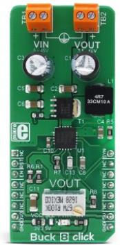
Buck 8 click is a high efficiency, wide voltage range, and high current synchronous step down (buck) DC-DC converter, featuring two enhanced modes that can be used to drive lighter loads with increased efficiency. The output voltage can be adjusted by the multi-turn trimmer potentiometer. Since the output voltage is set mechanically, it will retain the set value, even after the restart. Very high efficiency results with the reduced power dissipation, thus allowing reasonably high power to be delivered to the load, connected to the output terminal. Internal feedback compensation across the whole voltage range allows lower number of external components.
Equipped with a number of different protection features such as the overload protection, thermal protection, soft startup, this step-down converter offers a very secure and convenient way of reducing the input voltage to a level necessary for the operation of any low voltage application. It provides a clean, low noise and reliable power source. It can be used for different types of power supplies, regulation of the wall transformers output, single board applications powered by high voltage, and for any application that requires clean and efficient step-down voltage conversion.
How does it work?
Buck 8 click uses the MAX17536, a high-efficiency, synchronous step-down DC-DC converter with internal compensation, from Maxim Integrated. The MAX17536 is an advanced integrated step-down converter, which is able to deliver reasonably high current, up to 4A. The input voltage can range between 5V and 45V. It should stay roughly about 10% above the desired output voltage. This means that the output voltage ranges from the 0.9V up to 0.9 x Vin, where Vin is the input voltage.
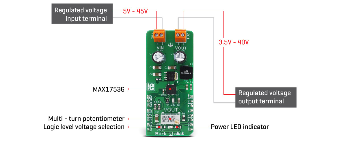
The output voltage can be adjusted by a precise multi-turn potentiometer. This potentiometer allows adjustment of the output voltage level by changing the resistance value of the voltage divider that feeds part of the output voltage back to the FB pin of the MAX17536. Since the potentiometer is a mechanical component, it will allow the output voltage to remain the same, even after the power cycle.
Although it can deliver up to 4A, the output current is limited by the maximum power dissipation of the converter. Although the percentage of the power lost on dissipation varies with both input voltage and output current, it can be assumed that this power loss is roughly 10%. According to the datasheet, maximum advisable power dissipation is 2.67W. To allow for some overhead, it is safe to assume that the maximum power dissipation is 2W. This means that the maximum output power is about 20W. Bearing this in mind, the maximum advisable output current will depend on the output voltage, according to the following equation:
Iout = P/Vout
This function represents the Safe Operating Area (SOA) and it is graphically illustrated on the bottom side of the Click board™. It holds true for Vin = 45V and switching frequency of 450kHz.
The MAX17536 features a robust overload and short circuit protection. When the internally set current limit of 6.5A is exceeded, the high side MOSFET is turned off and the hiccup mode is triggered. This mode suspends the operation for 32,768 duty cycles after which the soft start sequence is reattempted. If the fault condition is present at the startup and the output voltage remains under 68% of the nominal value, the hiccup mode is also activated.
The thermal protection ensures that the junction temperature of the IC stays below 165°C. When this temperature is exceeded, the device shuts down, allowing it to cool down. When the junction temperature drops for about 10°C, the device is restarted.
The condition of the output voltage can be monitored via the #RESET pin of the MAX17536. This pin is an open drain output and it is pulled to a HIGH logic level by the onboard resistor. It is routed to the RST pin of the mikroBUS™ and can be used as the power good indication. When the output voltage drops below 92.2% of the nominal regulated output voltage, this pin is driven to a LOW logic level. Thermal shutdown event is also reported by the #RESET pin.
The soft start feature prevents the inrush current. This feature is determined by the soft start capacitor. The soft start is set to about 18ms by the 100nF capacitor.
The SYNC/MODE pin is pulled to a high logic level, allowing the device to work in the DCM light load mode, allowing more efficient operation when the light load is connected to the output. By driving the MODE/SYNC pin to a LOW logic level, the device is forced into the PWM mode, which allows the least noise and ripple on the output, but it is not that efficient when working with light loads. The MODE/SYNC pin is routed to the PWM pin of the mikroBUS™ and it is pulled to a HIGH logic level by the onboard pull-up resistor. The device latches the state of this pin at the startup, and it ignores pin state changes after the startup sequence is finished.
One of the distinctive features of this buck converter is the ability to synchronize the switching clock frequency with an external clock signal. It is possible to synchronize the switching frequency within a range of about 1.1 to 1.4higher than the value set on the Buck 8 click, which is 450kHz. This feature is primarily used to synchronize switching frequencies when more than one buck converter is used. When the valid synchronization signal is applied to the MODE/SYNC pin, the device is going to switch to the PWM mode, with the switching frequency synchronized with the input signal. In this case, after the synchronization signal is disconnected, the device will remain working in the PWM mode.
The EN pin of the MAX17572 is routed to the CS pin of the mikroBUS™. This pin is used to enable the buck converter when driven to a HIGH logic level, but it can also be used to set the undervoltage lockout threshold. If the input voltage falls under this threshold, the internal low drop output regulators (LDOs) will not power on the internal logic and the buck converter will stay disabled.
The Buck 8 click features an SMD jumper, which is used to set the logical voltage levels for the pins, allowing both 3.3V and 5V MCUs to be used with the Click board™. The board is also equipped with the input and output screw terminals, which allow secure connection of the input voltage source and the load.
Specifications
| Type |
Buck |
| Applications |
Wall transformer voltage regulators, general purpose power supplies, distributed supply regulators, and similar applications where a high current buck converter with a wide input voltage range, is required. |
| On-board modules |
MAX17536, a high-efficiency, synchronous step-down DC-DC converter with internal compensation, from Maxim Integrated |
| Key Features |
Wide input voltage range, adjustable output voltage, overcurrent protection, thermal protection, soft start, adjustable PWM switching frequency, very high efficiency, low external components count, etc. |
| Interface |
GPIO |
| Input Voltage |
3.3V,5V |
| Click board size |
L (57.15 x 25.4 mm) |
Pinout diagram
This table shows how the pinout on Buck 8 click corresponds to the pinout on the mikroBUS™ socket (the latter shown in the two middle columns).
| Notes | Pin |  | Pin | Notes |
|---|
|
NC |
1 |
AN |
PWM |
16 |
SYN |
MODE/SYNC pin |
| Buck output fault signal |
RST |
2 |
RST |
INT |
15 |
NC |
|
| Enable outout voltage |
EN |
3 |
CS |
RX |
14 |
NC |
|
|
NC |
4 |
SCK |
TX |
13 |
NC |
|
|
NC |
5 |
MISO |
SCL |
12 |
NC |
|
|
NC |
6 |
MOSI |
SDA |
11 |
NC |
|
| Power supply |
+3.3V |
7 |
3.3V |
5V |
10 |
+5V |
Power supply |
| Ground |
GND |
8 |
GND |
GND |
9 |
GND |
Ground |
Buck 8 click electrical specifications
| Description | Min | Typ | Max | Unit |
|---|
| Input Voltage |
5 |
- |
45 |
V |
| Output voltage |
3.5 |
- |
40 |
V |
| Output current |
- |
- |
4 |
A |
Onboard settings and indicators
| Label | Name | Default | Description |
|---|
| LD1 |
PWR |
- |
Power LED indicator |
| JP1 |
VCC SEL |
Left |
Logic level voltage selection: left position 3.3V, right position 5V |
Software support
We provide the library for Buck 8 click on our LibStock page, as well as the demo application (example), developed using MikroElektronika compilers and mikroSDK. The provided click library is mikroSDK standard compliant. The demo application can run on all the main MikroElektronika development boards.
Library Description
The library carries functions related to GPIO pins control of the Buck 8 click. PWM control is not part of the library and should be initialized depending on the development system.
Key functions:
void buck8_setMode(uint8_t mode) - Set working mode.void buck8_enable( uint8_t state ) - Returns the status of the Click board™.
Examples Description
The demo application is composed of three sections:
- System Initialization - Initialization of the CS and RST pin as INPUT.
- Application Initialization - Initialization Driver init and set PWM frequency on 450kHz (OPEN mode).
- Application Task - (code snippet) - Logs the message to USBUART if the voltage is greater than the maximum setpoint value.
void applicationTask()
{
 if( buck8_getState() && flag == 0)
 {
 mikrobus_logWrite("max range ",_LOG_LINE);
 flag = 1;
 }
 else
 {
 flag = 0;
 }
 Delay_1sec();
}
The full application code and ready-to-use projects can be found on our LibStock page.
Other MikroElektronika libraries used in the example:
Additional notes and information
Depending on the development board you are using, you may need USB UART click, USB UART 2 click or RS232 click to connect to your PC, for development systems with no UART to USB interface available on the board. The terminal available in all MikroElektronika compilers, or any other terminal application of your choice, can be used to read the message.
mikroSDK
This click board is supported by the mikroSDK - MikroElektronika Software Development Kit. To ensure proper operation of mikroSDK compliant click board demo applications, the mikroSDK should be downloaded from the LibStock and installed for the compiler you are using.
For more information about mikroSDK, visit the official page.