Nano Power 2 click is a very low power voltage comparator, aimed at portable and battery-powered applications. It allows detecting a difference of two voltage potentials, applied on two input pins. The device can detect differences very precisely, avoiding oscillations that can occur when both input voltages are equal by employing an internal hysteresis. Nano Power 2 click offers a choice to select one of the input voltages from the internal fixed reference of 1.2V, or by setting both input voltages by the onboard potentiometers.
The current consumption of the Nano Power 2 click ensures that there is no significant load to the measured inputs, and compared to other similar devices, it is several magnitudes lower. It produces clean output signals, which are used to indicate the result of the comparison. Both the logic level and the power supply levels can be selected between 3.3V and 5V, allowing a wide range of MCUs to be used with this Click board™. With its two high-quality potentiometers, this Click board™ represents a unique testing platform for the integrated nanoPower comparator IC used on the Nano Power 2 click.
How does it work?
The Click board™ is equipped with an integrated comparator IC, labeled as MAX40000AUT12+, a nanoPower comparator with built-in reference, produced by Maxim Integrated. This company offers several variants of the same IC, of which the used IC variant offers reference voltage of 1.2V on one of its pins. This reference voltage can be used at the comparator input, providing an accurate reference voltage throughout the fully operational temperature range, if required by the custom application.
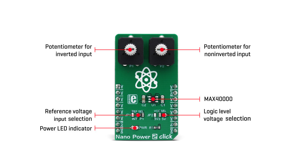
The IC itself requires a very low number of external components. It has two input pins, used as the comparator inputs. Each of these inputs can use -0.2V up to VCC + 0.2V. The VCC is the power supply voltage, and it can be selected via the SMD jumper labeled as LOGIC, between the 3.3V and 5V rails from the mikroBUS™. One of the comparator inputs, labeled as IM on the MAX40000 IC, is routable to either the onboard potentiometer (P1) or the REF pin of the IC, which provides the referent voltage of 1.2V. The routing can be done by another SMD jumper, labeled as REF SEL. The second comparator input (labeled as IP on the MAX40000 IC) is routed to the second onboard potentiometer (P2). Both potentiometers can be used to set any voltage between the GND and VCC, which is selected by the LOGIC jumper, as described above.
As mentioned before, the comparator has two inputs. One of them it is the inverting input and it is labeled as IM. The other input is a non-inverting input, labeled as IP. When the IP voltage becomes higher than the IM voltage, the output state becomes logic HIGH; otherwise, the output is set to a LOW state. A special case is when both voltages are very close, or at the same level, at any given moment. This would result in an appearance of oscillation at the output due to noise or parasitic feedback. To cope with this problem, an internal hysteresis of ±2.5mV is applied.
The output of the MAX40000 IC is routed to the mikroBUS™ INT pin, labeled as OUT on the Click board™. The output stage employs a unique break-before-make topology, capable of rail-to-rail operation with up to ±2mA loads. The output stage also uses a unique design, which minimizes supply current surges when the switching occurs, resulting in very clean output and low EM radiation. The MAX40000 has a push-pull output stage topology, which can both sink and source the current.
Working with the Nano Power 2 click is very easy and straightforward. Only a single pin is used, which can be used to either trigger an interrupt (therefore it is routed to the INT pin), or its status can be read via the input pin of the host MCU. However, MikroElektronika provides a library that contains a function which can be used for simplified control of the Nano Power 2 click. The library also contains an example application, which demonstrates the use of the function. This example application can be used as a reference for custom designs.
Specifications
| Type |
Linear |
| Applications |
It can be used for a voltage level comparison between two comparator pins, selectable by a potentiometer, or from the internal reference voltage pin. |
| On-board modules |
MAX40000, a nanoPower comparator with built-in reference, produced by Maxim Integrated |
| Key Features |
Two high quality potentiometers for selecting the voltage at the comparator pins, an accurate reference voltage of 1.2V, hysteresis which prevents erratic behavior when the input voltages are close to each other. |
| Interface |
GPIO |
| Input Voltage |
3.3V,5V |
| Click board size |
M (42.9 x 25.4 mm) |
Pinout diagram
This table shows how the pinout on Nano Power 2 click corresponds to the pinout on the mikroBUS™ socket (the latter shown in the two middle columns).
| Notes | Pin |  | Pin | Notes |
|---|
|
NC |
1 |
AN |
PWM |
16 |
NC |
|
|
NC |
2 |
RST |
INT |
15 |
OUT |
Comparator OUT |
|
NC |
3 |
CS |
RX |
14 |
NC |
|
|
NC |
4 |
SCK |
TX |
13 |
NC |
|
|
NC |
5 |
MISO |
SCL |
12 |
NC |
|
|
NC |
6 |
MOSI |
SDA |
11 |
NC |
|
| |
NC |
7 |
3.3V |
5V |
10 |
+5V |
Power supply |
| Ground |
GND |
8 |
GND |
GND |
9 |
GND |
Ground |
Nano Power 2 click electrical specifications
| Description | Min | Typ | Max | Unit |
|---|
| Input reference voltage |
- |
1.2 |
- |
V |
Onboard settings and indicators
| Label | Name | Default | Description |
|---|
| LD1 |
PWR |
- |
Power LED indicator |
| JP1 |
REF SEL |
Right |
Reference voltage source selection: left position internal reference voltage, right position P1 voltage |
| JP2 |
LOGIC |
Right |
Power supply / logic voltage level selection: left position 3.3V, right position 5V |
Software support
We provide a demo application for Nano Power 2 click on our Libstock page, as well as a demo application (example), developed using MikroElektronika compilers. The demo can run on all the main MikroElektronika development boards.
Library Description
Library initializes and defines GPIO driver and performs control of device voltage.
For more details check the documentation.
Key functions:
NANOPW2_RETVAL_T nanopw2_checkOutput( void ) - TFunction gets output voltage from comparator.
Example description
The application is composed of three sections:
- System Initialization - Initializes OUT (INT) pin as an input.
- Application Initialization - Initializes GPIO driver.
- Application Task - (code snippet) - Checks the comparator's output and logs output value on USB UART. The hysteresis in a comparator creates two trip points: one for upper threshold (VTRIP+) and one for lower threshold (VTRIP-) for voltage transitions on the input signal. When the comparator's input voltages are equal, the hysteresis effectively causes one comparator input to move quickly past the other, thus taking the input out of the region where oscillation occurs. The output voltage is high (1) when noninverted input voltage rises above the hysteresis and stays high until noninverted input voltage falls below the hysteresis. Then the output goes low and stays low until noninverted input voltage rises above the hysteresis. This is an example where the inverted input voltage is fixed and the noninverted input voltage is varied. If the inputs were reversed, the example would be the same, except with an inverted output.
void applicationTask()
{
 outCheck = nanopw2_checkOutput();
 if (outCheck != outCheckPrev)
 {
 WordToStr( outCheck, text );
 mikrobus_logWrite( "OUT is: ", _LOG_TEXT );
 mikrobus_logWrite( text, _LOG_LINE );
 outCheckPrev = outCheck;
 }
}
The full application code, and ready to use projects can be found on our Libstock page.
Additional notes and information
Depending on the development board you are using, you may need USB UART click, USB UART 2 click or RS232 click to connect to your PC, for development systems with no UART to USB interface available on the board. The terminal available in all MikroElektronika compilers, or any other terminal application of your choice, can be used to read the message.
mikroSDK
This click board is supported by mikroSDK - MikroElektronika Software Development Kit. To ensure proper operation of mikroSDK compliant click board demo applications, mikroSDK should be downloaded from the LibStock and installed for the compiler you are using.
For more information about mikroSDK, visit the official page.