To use Click Analyzer, it is enough to connect it with the USB cable to the host PC. It will register itself as the serial adapter on a specific COM port, offering the analysis data in several output formats. This allows Click Analyzer to perfectly fit in any development scenario, offering the full insight into the mikroBUS™ inner workings to users, with no additional equipment required. Additional four LEDs can be used to quickly indicate logic states on any of the 14 pins of the mikroBUS™. With its powerful and simple to use functions, compact size, and a support for several popular input and output protocols, Click Analyzer represents an irreplaceable tool for both the development and troubleshooting.
How does it work?
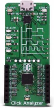
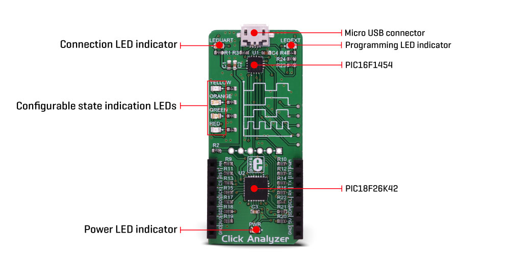
As already mentioned, Click Analyzer consists of two MCUs, labeled as PIC18F26K42 and PIC16F1454, both from Microchip. These 8-bit MCUs both have their specific features which allow fast, reliable and accurate readings of the mikroBUS™ pin states, offering the output data in several formats. PIC18F26K42 offers several powerful peripheral modules best suited for the analysis and fast data transfer, such as the Direct Memory Access (DMA), Configurable Logic Cells (CLC), Signal Measurement Timers (SMT), Numerically Controlled Oscillators, and more. The second MCU labeled as PIC16F1454 is best suited for the data communication via the USB, so it is used to format and output the analysis data.
When connected via the USB port with the micro USB cable, the device will register itself as the serial adapter on a specific COM port, assigned by the operating system of the host computer. The data will be transferred between the Click Analyzer and the host computer by using this port. Click Analyzer has a message format autodetection feature and is able to set itself to a specific mode, depending on the incoming message format.
Click Analyzer supports several communication protocols, each used to define the input and output data format:
- Web mode, a default mode which offers JSON formatted data on the output
- Terminal mode, a minimalistic GUI for a direct human interface for ANSI terminals
- Binary mode, best suited for the M2M communication with highest data throughput
In addition, depending on the specified serial communication parameters, the device can operate in three operating modes:
- Baud Rate = 4800 - starts the XBOOT bootloader
- 4800 < Baud Rate = 115200 - resets the Click Analyzer and send the welcome message
- 115200 < Baud Rate - connects the device in the current state
The simplest form of a communication is the Terminal mode. This mode allows to use a standard modem terminal application (such as PuTTY), formatting the message responses according to the ANSI/XTERM protocol. The terminal application should be able to provide the support for the CP437 character set, in order to display the Click Analyzer output and command responses without any glitches. This mode offers a basic functionality for building HMI (Human-Machine Interface) based applications. However, this mode is not recommended to be used for the Machine-to-Machine (M2M) applications, as there are other, more complex and robust communication modes, such as the Web mode and Binary mode, which offer responses encapsulated in the CRC protected response structure, a properly JSON formatted responses, or a combination of the two (JSON messages, encapsulated in a CRC protected response structure). This allows building reliable and fast M2M applications or powerful JSON based web applications with a customized interface.
Click Analyzer has one stackable mikroBUS™ slot, so it is able to have any Click board™ equipped while being installed in the mikroBUS™ slot of a development system at the same time. This allows so-called "data sniffing" or capturing the data as it is being transferred between the equipped Click board™ and the development system. In this scenario, the Click Analyzer acts as the "middle man", exposing the communication to the user via the serial COM port of the host computer.
By sending a specific command, the analyzer is able to display the logic states on each mikroBUS™ pin, acting as the Logic Scope. The Logic Scope (LS) function performs sampling of the logic states on all pins with the configurable sampling frequency, which can go up to 4 MHz. It is also possible to specify the number of samples before the analysis is sent out. The Logic Scope function allows to monitor states of the pins, while the Click board™ is exchanging data with the development system, or to simply analyze if the development system sets the expected states on its mikroBUS™ pins, regardless if the Click board™ is connected to it or not. This simplifies troubleshooting and debugging a lot, offering a unique opportunity to monitor and analyze the functionality in a real-life usage scenario.
Another important function of the Click Analyzer is the Digital Voltage Meter (DVM). This allows an accurate voltage level monitoring for up to 5V. This can be used to monitor voltage levels on the pins or to log the pin voltage values during a specific time interval. The voltage can be monitored on each of the 14 mikroBUS™ pins, including the +5V and +3.3V power rails.
Pin state change can be visualized by utilizing one of the four differently colored LEDs. Each LED can be assigned to any of the 14 available mikroBUS™ pins. A LED will be pulsed on the rising or falling edge of the pin, indicating the state change. It won't be lit if the state of the pin is constant (unchanged). This can be used to visually inspect the state changes on the pins, and thanks to the different coloring of the LEDs, the state change can be noticed instantaneously, without counting up the LEDs or checking out the silk labels.
A note should be made that the Click Analyzer does not require any specific firmware. It works in an out-of-the-box manner. As soon as it is connected via the USB cable, it will become available for the monitoring purposes. Its responses, however, can be implemented in any type of end-user application. For the evaluation purposes, the XTERM protocol, the simplest of the output protocols is used to demonstrate the functionality of the device in a freeware terminal application such as the PuTTY.
How to use a terminal application for quick evaluation of the Click Analyzer
As already mentioned, the simplest way to use the Click Analyzer is by using a terminal application, since it offers simple HMI (human-machine interface). The output of the Click Analyzer will contain data strings using the CP437 character set, so the first step is to configure the terminal application properly. For this purpose, a small freeware application called PuTTY can be used. PuTTY is a free SSH and telnet client for Windows operating system.
- Download PuTTY application from their official web page: https://www.putty.org/
- Install the application
- Insert the Click Analyzer into the mikroBUS™ socket and plug in the USB cable
- Check the COM port it was assigned to
- Run the PuTTY application
When the Click Analyzer is connected over the USB, the LED labeled as the LED UART will indicate the connection. The PuTTY will open the configuration window by default. It is accessed by clicking the Session option in the options tree on the left side of the configuration window. Use Serial as the "Connection Type", and in the "Serial Line" field, the COM port of the Click Analyzer should be entered. The assigned COM port can be discovered by using the Device Manager (Windows). Once this is done, navigate to "Translation" in the left-side options tree. Select the CP437 as the "Remote Character Set". When this is done, click the OPEN button on the bottom, and if everything is configured properly, a session window should pop-up containing the terminal header, as shown in the image below.
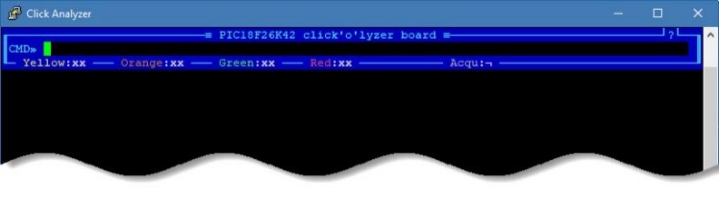
Click Analyzer session window
Now, the terminal is ready to accept some basic commands. You can experiment by using commands such as the DVM (Digital Voltmeter function), LS FREQ=100K (Logic Scope function, set at 100 kHz), LED YELLOW=5 (Yellow LED assigned to a pin number 5). The header offers some basic info, including the LED assignment. You can also use the mouse to click the Acqu: label in the header, which will allow continuous measurements to be made. Else only a single measurement will be performed after entering a command. It is worth mentioning some simple terminal command strings. For example, typing COMMANDS will return a response with a list of all the available XTERM commands. Typing GET <command>_INFO returns a response with the available parameters available for the specified command (e.g. GET DVM_INFO). All the required documentation, including a detailed manual covering all the existing protocols, can be found in the download links, below.
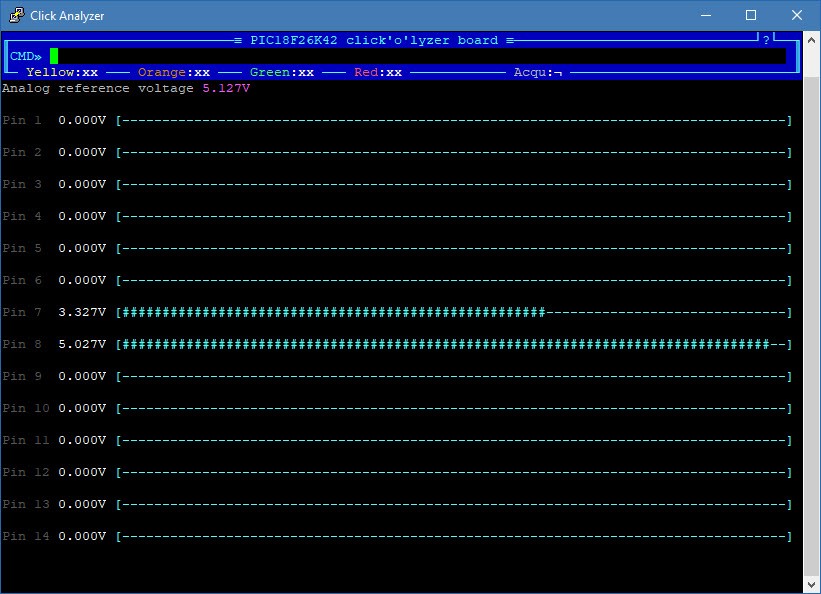
A session window showing DVM command terminal response
Specifications
| Type |
Shield |
| Applications |
It can be used as a replacement for bulky analyzing equipment when working with applications that have mikroBUS™ socket incorporated into their design. It can provide accurate and simple voltage and logic measurements, providing feedback over the USB port, offering different formatting protocols |
| On-board modules |
PIC16F1454, an 8-bit MCU; PIC18F26K42, an 8-bit MCU, both from Microchip |
| Key Features |
High speed accurate measurements right from the mikroBUS™ slot, compact size replacement for the bulky analyzing equipment, output message formatting by using various HMI and M2M protocols, pass-through mikroBUS™ socket for Click board™ communication "sniffing", diagnostic, and more |
| Interface |
GPIO,USB |
| Input Voltage |
3.3V,5V |
| Click board size |
L (57.15 x 25.4 mm) |
Pinout diagram
This table shows how the pinout on Click Analyzer corresponds to the pinout on the mikroBUS™ socket (the latter shown in the two middle columns).
| Notes | Pin |  | Pin | Notes |
|---|
| mikroBUS™ PIN 1 I/O |
AN |
1 |
AN |
PWM |
16 |
PWM |
mikroBUS™ PIN 14 I/O |
| mikroBUS™ PIN 2 I/O |
RST |
2 |
RST |
INT |
15 |
INT |
mikroBUS™ PIN 13 I/O |
| mikroBUS™ PIN 3 I/O |
CS |
3 |
CS |
RX |
14 |
TX |
mikroBUS™ PIN 12 I/O |
| mikroBUS™ PIN 4 I/O |
SCK |
4 |
SCK |
TX |
13 |
RX |
mikroBUS™ PIN 11 I/O |
| mikroBUS™ PIN 5 I/O |
SDO |
5 |
MISO |
SCL |
12 |
SCL |
mikroBUS™ PIN 10 I/O |
| mikroBUS™ PIN 6 I/O |
SDI |
6 |
MOSI |
SDA |
11 |
SDA |
mikroBUS™ PIN 9 I/O |
| mikroBUS™ PIN 7 I/O |
3.3V |
7 |
3.3V |
5V |
10 |
5V |
mikroBUS™ PIN 8 I/O |
| Ground |
GND |
8 |
GND |
GND |
9 |
GND |
Ground |
Onboard settings and indicators
| Label | Name | Default | Description |
|---|
| PWR |
PWR |
- |
Power LED indicator |
| LEDEXT |
LEDEXT |
- |
Programming LED indicator |
| LEDUART |
LEDUART |
- |
Connection LED indicator |
| YELLOW |
YELLOW |
- |
Assignable LED, Yellow |
| ORANGE |
ORANGE |
- |
Assignable LED, Orange |
| GREEN |
GREEN |
|
Assignable LED, Green |
| RED |
RED |
- |
Assignable LED, Red |