Equipped with the intelligent power management and battery fuel gauge ICs, this Click board™ is the complete power solution for many embedded and consumer applications that rely on the efficient power ORing and an advanced battery charging functionality. Charger 8 click can be used as a part of the power supply and distribution system in many applications: different kinds of handheld appliances, portable media players, portable audio players, and other general-purpose battery-operated electronic devices.
How does it work?
Charger 8 click is based on two different ICs: It uses the MAX8903B, an integrated single cell Li-Ion/Li-Po battery charger for USB and external power, as well as the MAX17201, a stand-alone battery fuel gauge with SHA-256 authentication, both ICs from Maxim Integrated.

The MAX8903B is labeled as U1, and it provides the majority of functions for this Click board™. Its basic task is to provide power for the system load and charge a single-cell Li-Ion/Li-Po battery, connected at the standard 2.5mm pitch XS battery connector, labeled as BAT. When the USB input is used as a primary power source, the MAX8903B will try to maintain the system current by utilizing the connected battery or the external power supply unit (PSU) at the VIN input. On the other hand, it will try to redirect all the unused power to the battery charging section in cases when the system requires lower current levels. With the help of the Smart Power Selector™ technology, it will always choose the best path in order to utilize the limited power resources in the most efficient way.
The MAX8903B is designed with reliability in mind: the IC prevents draining the battery below the critical level, protects it from overheating (if thermistor is used), offers prequel charging (for deeply depleted batteries), features an overvoltage protection, charging status monitoring and so on. The Click board™ itself is equipped with a set of indicators used to monitor both charging process and power distribution.
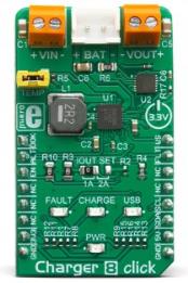
- USB LED indicates that there is a valid voltage at the USB input. Instead to the USB connector, the USB power supply input pin of the MAX8903B is connected to the mikroBUS™ 5V power rail.
- CHARGE LED indicates the charge-in-progress status.
- FAULT LED indicates an error during charging process.
Besides the FAULT LED indicator, the FAULT pin of the MAX8903B is also routed to the mikroBUS™ INT pin, allowing an interrupt to be generated on the host MCU in case of a charging failure. This pin will be pulled to a LOW logic level when the charging timer expires while the charger is still in prequel mode (mode in which only 10% of charging current is applied to the battery, while it is deeply discharged), or while the battery stays in fast-charging mode.
DOK pin is routed to the mikroBUS™ AN pin, labeled as DOK. A logic LOW level on this pin indicates that there is a valid power supply at the DC power supply input pin of the MAX8903B. If there is a PSU connected to the VIN terminal, its voltage should stay within the valid range. The undervoltage/overvoltage protection will be activated if the internal voltage threshold is exceeded. The absolute maximum voltage rating of the MAX8903B is 20V.
USB Suspend (USUS) pin from the MAX8903B is routed to the mikroBUS™ PWM pin, and it is labeled as US. It is used to suspend the power source connected to the USB power supply input pin. With no external PSU connected, setting this pin to a HIGH logic level will disable the battery charger and the SYS output, allowing the USB SUSPEND mode.
The CEN pin is used to disable the charging circuitry. It is pulled to a LOW logic level by a resistor, and the MAX8903B should be controlling this pin internally for optimum performance. However, if battery charging is not wanted, it can be forced off by pulling this pin to a HIGH logic level. It is routed to the mikroBUS™ pin CS and labeled as EN.
The MAX17201 IC offers a battery gauge functionality, allowing to monitor the performance of the connected battery. It employs a proprietary ModelGauge™ m5 algorithm, which allows very accurate monitoring of all battery parameter, including the predicted aging time, remaining cycles and so on. It has a programmable ALERT function which is signaled over the ALTR1 pin, routed to the mikroBUS™ RST pin, labeled as ALT. The MAX17201 IC uses the I2C interface to communicate with the host MCU.
Specifications
| Type |
Battery charger |
| Applications |
It can be used as a part of the power supply and distribution system in many applications: different kinds of handheld appliances, portable media players, portable audio players, and other general-purpose battery-operated electronic devices. |
| On-board modules |
MAX8903B, an integrated single cell Li-Ion/Li-Po battery charger for USB and external power; MAX17201, a stand-alone battery fuel gauge with SHA-256 authentication, both ICs from Maxim Integrated. |
| Key Features |
Charger 8 click is designed for a safe and efficient charging of Li-Po / Li-ion batteries, and optimized power management and distribution. Dedicated battery fuel gauge IC with advanced measurement and prediction algorithms. Selectable charging current up to 2A. |
| Interface |
GPIO,I2C |
| Input Voltage |
3.3V,5V |
| Click board size |
M (42.9 x 25.4 mm) |
Pinout diagram
This table shows how the pinout on Charger 8 Click corresponds to the pinout on the mikroBUS™ socket (the latter shown in the two middle columns).
| Notes |
Pin |
 |
Pin |
Notes |
|---|
| External PSU OK |
DOK |
1 |
AN |
PWM |
16 |
US |
USB Suspend |
| Battery Gauge Alert |
ALT |
2 |
RST |
INT |
15 |
FLT |
Fault Indicator |
| Charger Enable |
EN |
3 |
CS |
RX |
14 |
NC |
|
| |
NC |
4 |
SCK |
TX |
13 |
NC |
|
| |
NC |
5 |
MISO |
SCL |
12 |
SCL |
I2C Clock |
| |
NC |
6 |
MOSI |
SDA |
11 |
SDA |
I2C Data |
| Power Supply |
3V3 |
7 |
3.3V |
5V |
10 |
5V |
Power Supply |
| Ground |
GND |
8 |
GND |
GND |
9 |
GND |
Ground |
Charger 8 Click electrical specifications
| Description |
Min |
Typ |
Max |
Unit |
|---|
| Input Voltage (at VIN terminal) |
4.6 |
5 |
6 |
V |
| System output voltage (at VOUT terminal) |
4.265 |
|
4.395 |
V |
| Charging Current (max current selectable by IOUT SEL) |
0.5 |
|
1 (2) |
A |
Onboard settings and indicators
| Label |
Name |
Default |
Description |
|---|
| LD1 |
PWR |
- |
Power LED indicator |
| LD2 |
FAULT |
- |
Charger fault LED indicator |
| LD3 |
CHARGE |
- |
Charger status LED indicator |
| TB1 |
VOUT |
- |
System power supply output |
| TB2 |
VIN |
- |
External PSU input connector |
| J1 |
BAT |
- |
2.5mm pitch standard battery XS connector |
| J2 |
TEMP |
- |
Optional battery thermistor connector |
| JP1 |
IOUT SEL |
Left |
Current limit selection for the battery charger: left position 1A, right position 2A |
Software support
We provide a library for the Charger 8 Click on our LibStock page, as well as a demo application (example), developed using MikroElektronika compilers. The demo can run on all the main MikroElektronika development boards.
Library Description
The library initializes and defines the I2C bus driver and drivers that offer a choice for writing data in register/NV memory and reading data from register/NV memory. The library includes function to read the battery diagnostics. The user can set the maximum battery capacity to have a good reading of the current capacity of the battery. The user has a function for enable/ disable device, sets Alert mode and usb suspand mode.
Key functions:
void charger8_enable(uint8_t enable) - Functions for enable or disable device.float charger8_getCurrent() - Functions for reading the current charging battery.float charger8_getVoltage() - Functions for reading the voltage of the battery.void charger8_reset() - General reset procedure.
Examples description
The application is composed of the three sections :
- System Initialization - Initializes I2C module and sets CS pin, RST pin and PWM pin as OUTPUT and INT pin as INPUT.
- Application Initialization - Initialization driver init, enable moduele and default configuration, disable ALERT and USB suspand mode and sets max battery capacity.
- Application Task - (code snippet) - Reads battery diagnostics and this data logs to USBUART every 1500 ms.
Note: The user can charge a battery internally over mikroBUS or externally by supplying the VIN connectors with 5V. For more precise diagnosis and easier tracking of the charging battery status you can set its capacity - e.g. if you have a 2000mAh battery you can use the "charger8_setMaxBatteryCapacity()" function and pass the parameter for 2000mAh, by doing this you make the readings more precise. In the example we used only some possibilities of the diagnostics like temperature of the chip during charging, charging current, current battery voltage, current battery capacity and how much the battery is charged in percentage. In case of changing the battery to a different one, it is neccessary to reset the device and set the battery's maximum capacity.
void applicationTask()
{
    float Temperature;
    float Current;
    float Voltage;
    uint8_t SOC;
    uint16_t Capacity;
    char demoText[50];

    mikrobus_logWrite(" - Battery diagnostics - ", _LOG_LINE);
    /* Temperature */
    Temperature = charger8_getTemperature();
    FloatToStr(Temperature, demoText);
    mikrobus_logWrite(" - Temperature : ", _LOG_TEXT);
    mikrobus_logWrite(demoText, _LOG_TEXT);
    mikrobus_logWrite(" C ", _LOG_LINE);
    /* Current */
    Current = charger8_getCurrent();
    FloatToStr(Current, demoText);
    mikrobus_logWrite(" - Current : ", _LOG_TEXT);
    mikrobus_logWrite(demoText, _LOG_TEXT);
    mikrobus_logWrite(" mA ", _LOG_LINE);
    /* Voltage */
    Voltage = charger8_getVoltage();
    FloatToStr(Voltage, demoText);
    mikrobus_logWrite(" - Voltage : ", _LOG_TEXT);
    mikrobus_logWrite(demoText, _LOG_TEXT);
    mikrobus_logWrite(" mV ", _LOG_LINE);
    /* Capacity */
    Capacity = charger8_getCapacity();
    IntToStr(Capacity, demoText);
    mikrobus_logWrite(" - Capacity : ", _LOG_TEXT);
    mikrobus_logWrite(demoText, _LOG_TEXT);
    mikrobus_logWrite(" mAh ", _LOG_LINE);
    /* SOC */
    SOC = charger8_getSOC();
    IntToStr(SOC, demoText);
    mikrobus_logWrite(" - SOC : ", _LOG_TEXT);
    mikrobus_logWrite(demoText, _LOG_TEXT);
    mikrobus_logWrite(" % ", _LOG_LINE);

    mikrobus_logWrite(" -------------------------- ", _LOG_LINE);
    Delay_ms( 1500 );
}
The full application code, and ready to use projects can be found on our LibStock page.
Other mikroE Libraries used in the example:
Additional notes and informations
Depending on the development board you are using, you may need USB UART click, USB UART 2 click or RS232 click to connect to your PC, for development systems with no UART to USB interface available on the board. The terminal available in all MikroElektronika compilers, or any other terminal application of your choice, can be used to read the message.
mikroSDK
This click board is supported with mikroSDK - MikroElektronika Software Development Kit. To ensure proper operation of mikroSDK compliant click board demo applications, mikroSDK should be downloaded from the LibStock and installed for the compiler you are using.
For more information about mikroSDK, visit the official page.