Charging of the Li+ battery cell is a demanding task that requires a very accurate current and voltage monitoring and limiting. In addition, it also requires specific charging conditions, depending on the battery level (constant current mode, constant voltage mode). Li+ batteries contain flammable chemical compounds and can easily be ignited. The MAX1757 IC closely monitors the battery voltage and current during the charging process, ensuring safe and reliable operation. Charger 9 click is a perfect solution for the development of multiple Li+ battery cell charging applications, offering a set of connectors, pins, and LED indicators, allowing fast and easy prototyping.
How does it work?
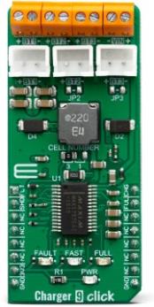
Charger 9 click is equipped with the MAX1757, a stand-alone, switch-mode Li+ battery charger, from Maxim Integrated. It can be used to charge one to three lithium-ion (Li+, Li-Po) batteries with up to 1.5A. The number of batteries can be selected by a set of onboard jumpers. The battery regulation voltage (VBATTR) is set to 4.2V per cell on this Click board™. High accuracy of the integrated voltage limiter ensures reliable charging and prevents over-charging of the connected cell. The charging process is closely monitored and regulated by the extensive state machine with the addition of two timers, protecting the system if damaged battery cells are connected.
.jpg)
Charger 9 click requires an external power supply for its operation. To prevent an undervoltage lockout, the input voltage of the external power supply (VIN) should be at least 100mV larger than the voltage at the BT outputs (BAT pin of the MAX1757 IC). This prevents discharging of the batteries if the power source voltage drops too low. The maximum allowed voltage at the VIN terminal of the Charger 9 click is 14V, while the input current limit is set to 2A.
As already mentioned, the MAX1757 uses an extensive state machine, which is explained in great details within the datasheet. However, the following is a brief summary of the description:
The battery voltage (VBATT) is monitored by the state machine. After the IC reset (power-up, etc.), the MAX1757 IC (charger) enters the so-called Prequalification mode. Based on the battery voltage level, as well as the voltage of the input power supply (VIN > VBATT), the state machine decides to start the charging process. If the battery cell is deeply discharged, the charger tries to restore it by using 1/10 of the full charging current.
Once the battery level is restored above the battery undervoltage level, and when all the other prerequisites are met, the charger starts the fast charging process, by switching to the Constant Current (CC) mode (limited to 1.5A on this Click board™). This mode is indicated by a yellow LED indicator labeled as FAST, as well as the LOW logic level at the CHG pin of the Click board™.
When the battery charge level reaches 85% approx. (when the VBATT reaches the VBATTR, set to 4.2V on this Click board™) the charger switches to the Constant Voltage (CV) mode. This is indicated by a blue LED indicator labeled as FULL, as well as the LOW logic level at the FUL pin of the Click board™. The charging current now starts to drop.
When the battery charge reaches 95% approx. (charging current falls below 330mA) the charger enters the Top-Off mode, turning off all the LED indicators (CHG and FUL pins are at the HIGH logic level). The charger is still operated in the CV mode.
After a timer expires, the charging process is done, and all the charging operations are stopped until the battery voltage drops under the recharge voltage threshold (VBATT = 95% of the VBATTR). When this happens, the IC gets reset and the state machine cycle is repeated.
Each charging phase has a time-out period: if the time-out period is exceeded, an error will be indicated by a red LED labeled as FAULT, as well as the LOW logic level at the FLT pin of the Click board™. An ongoing charging operation will be terminated to prevent any damage.
How to properly set the number of battery cells ?
The number of battery cells can be set by moving the SMD jumper labeled as CELL NUMBER to an appropriate position (1 or 3). To select two cells, the SMD jumper should be unpopulated. The number of physically connected cell batteries must correspond to the number of cells set by the CELL NUMBER jumper.
The CELL NUMBER jumper must be used in conjunction with two additional SMD jumpers, labeled as JP2 and JP3. These two jumpers are used to override unused connectors in the case when the number of battery cells is less than 3. If an unused connector is not overridden by a jumper, the GND path will be cut off from the connected battery (the battery cells are connected in series). By default, the number of battery cells is set to 3, so JP2 and JP3 should remain unpopulated. Charger 9 click offers XH type connectors as well as 2-pole terminal screw connectors, allowing to connect various types of Li+ batteries.
Specifications
| Type |
Battery charger |
| Applications |
Charger 9 click is a perfect solution for the development of multiple Li+ battery cell charging applications, offering a set of connectors, pins, and LED indicators, allowing fast and easy prototyping. |
| On-board modules |
MAX1757, a stand-alone, switch-mode Li+ battery charger, from Maxim Integrated |
| Key Features |
Designed for a safe and efficient charging of up to 3 Li-Po / Li-ion battery cells (selectable), an extensive state machine for reliable charging process, two types of battery connectors, charging state indicators over LEDs and mikroBUS™ pins, etc. |
| Interface |
GPIO |
| Input Voltage |
3.3V |
| Click board size |
M (42.9 x 25.4 mm) |
Pinout diagram
This table shows how the pinout on Charger 9 click corresponds to the pinout on the mikroBUS™ socket (the latter shown in the two middle columns).
| Notes |
Pin |
 |
Pin |
Notes |
|---|
| Fault Indicator |
FLT |
1 |
AN |
PWM |
16 |
CHG |
Fast charge state indicator |
| Charger IC Shutdown |
SHD |
2 |
RST |
INT |
15 |
FUL |
Full charge state indicator |
| |
NC |
3 |
CS |
RX |
14 |
NC |
|
| |
NC |
4 |
SCK |
TX |
13 |
NC |
|
| |
NC |
5 |
MISO |
SCL |
12 |
NC |
|
| |
NC |
6 |
MOSI |
SDA |
11 |
NC |
|
| Power Supply |
3.3V |
7 |
3.3V |
5V |
10 |
NC |
|
| Ground |
GND |
8 |
GND |
GND |
9 |
GND |
Ground |
Onboard settings and indicators
| Label |
Name |
Default |
Description |
|---|
| LD1 |
PWR |
- |
Power LED Indicator |
| LD2 |
FAULT |
- |
Charger FAULT LED indicator |
| LD3 |
FULL |
- |
Charger FULL status LED indicator |
| LD4 |
FAST |
- |
Charger FAST status LED indicator |
| BT1 - BT3 |
BT1 - BT3 |
- |
Li-Ion battery cell connection terminals |
| J1 - J3 |
BT1 - BT3 |
- |
Li-Ion battery cell XH connectors |
| JP1 |
CELL NUMBER |
Left |
Number of battery cells: left position for 3 battery cells, right position for 1 battery cell, unpopulated for 2 battery cells |
| JP2 - JP3 |
JP2 - JP3 |
Unpopulated |
Override jumpers: unpopulated for a used battery cell connector, populated for an unused battery connector |
Charger 8 click electrical specifications
| Description |
Min |
Typ |
Max |
Unit |
|---|
| Input Voltage (at VIN terminal) |
6 |
- |
14 |
V |
| Battery voltage regulation (per cell) |
4.167 |
4.2 |
4.233 |
V |
| Full-scale charging current |
1.35 |
1.5 |
1.65 |
A |
Software support
We provide a library for the Charger 9 click on our LibStock page, as well as a demo application (example), developed using MikroElektronika compilers. The demo can run on all the main MikroElektronika development boards.
Library Description
This library allows user to perform a control of the Charger 9 Click board. Also user can check the indication status from the charger to get charging state. Fault condition also can be checked. For more details check documentation.
Key functions:
void charger9_gpioDriverInit(T_CHARGER9_P gpioObj) - Convert ADC value to Pressure data in mBar.T_CHARGER9_RETVAL charger9_enable( T_CHARGER9_STATE pwr_state ) - Convert ADC value to Voltage in mV.T_CHARGER9_RETVAL charger9_faultInd( void ) - Sets max output voltage on the AN pin.
Examples description
The application is composed of three sections :
- System Initialization - Initializes peripherals and pins.
- Application Initialization - Initializes GPIO driver and turns OFF the charger as initial state.
- Application Task - (code snippet) - Checks which command was sent by user and performs the selected command. Also checks the fault condition, and when fault condition is detected sends a report message to the uart terminal and turns OFF the charger. Note: When user sends a desired command to the charger, a report message will be sent to the uart terminal as indication to the user. The possible commands, for Charger 9 control, will be written to the uart terminal. The alarm sound will be generated on the determined commands: enable, disable and fault condition detecting.
void applicationTask()
{
	rx_dat = UART_Rdy_Ptr();

	if (rx_dat != 0)
	{
		rx_dat = UART_Rd_Ptr();

		switch (rx_dat)
		{
			case 'e' :
			{
				if (en_flag == _CHARGER9_DISABLE)
				{
					charger9_enable( _CHARGER9_ENABLE );
					en_flag = _CHARGER9_ENABLE;

					mikrobus_logWrite( "** Charger 9 is enabled **", _LOG_LINE );
					alarmOn();
				}
				else
				{
					mikrobus_logWrite( "** Charger 9 is already enabled **", _LOG_LINE );
				}
			break;
			}
			case 'd' :
			{
				if (en_flag == _CHARGER9_ENABLE)
				{
					charger9_enable( _CHARGER9_DISABLE );
					en_flag = _CHARGER9_DISABLE;

					mikrobus_logWrite( "** Charger 9 is disabled **", _LOG_LINE );
					alarmOff();
				}
				else
				{
					mikrobus_logWrite( "** Charger 9 is already disabled **", _LOG_LINE );
				}
			break;
			}
			case 's' :
			{
				charge_state = charger9_fullChargeInd();

				if (charge_state == _CHARGER9_IND_ACTIVE)
				{
					mikrobus_logWrite( "** Full-Charge state **", _LOG_LINE );
				}

				charge_state = charger9_fastChargeInd();

				if (charge_state == _CHARGER9_IND_ACTIVE)
				{
					mikrobus_logWrite( "** Fast-Charge state **", _LOG_LINE );
				}
			break;
			}
			case 'l' :
			{
				writeLegend();
			break;
			}
			default :
			{
				mikrobus_logWrite( "** Invalid command **", _LOG_LINE );
				writeLegend();
			break;
			}
		}
	}

	charge_state = charger9_faultInd();

	if (charge_state == _CHARGER9_IND_ACTIVE)
	{
		charger9_enable( _CHARGER9_DISABLE );
		en_flag = _CHARGER9_DISABLE;

		mikrobus_logWrite( "** Fault condition! **", _LOG_LINE );
		mikrobus_logWrite( "** Charger 9 is disabled **", _LOG_LINE );
		alarmFault();
	}
}
Additional Functions :
- alarmOn - Generates an alarm sound for charger power ON.
- alarmOff - Generates an alarm sound for charger power OFF.
- alarmFault - Generates an alarm sound for fault condition.
- writeLegend - Writes possible valid commands to the uart terminal.
The full application code, and ready to use projects can be found on our LibStock page.
Other mikroE Libraries used in the example:
Additional notes and informations
Depending on the development board you are using, you may need USB UART click, USB UART 2 click or RS232 click to connect to your PC, for development systems with no UART to USB interface available on the board. The terminal available in all MikroElektronika compilers, or any other terminal application of your choice, can be used to read the message.
MIKROSDK
This click board is supported with mikroSDK - MikroElektronika Software Development Kit. To ensure proper operation of mikroSDK compliant click board demo applications, mikroSDK should be downloaded from the LibStock and installed for the compiler you are using.
For more information about mikroSDK, visit the official page.