Some operating procedures require switching of the electrical power to isolate a machine. After the power has been switched off the key can be released to take the next step, for example opening an access door. Keylock 2 click holds sealed mechanism that are mostly used in automated PC board processing and can be used as an actuator for various applications. If your project require rotary type of actuator Keylock 2 click board might be a perfect solution for you.
How does it work?
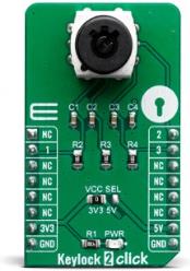
The Keylock 2 click uses SK13AEG13 switch keylock from the company NKK Switches, with three position output states. The key can be removed from the lock in any of the three positions. The Click board package contains two keys and one protective cap.

The SK13AEG13 key has hosing and brushing of high insulating material which withstands over 15 kilovolts of electrostatic discharge, thus providing antistatic protect for the main circuitry. This mechanism has mechanical life of 30,0000 cycles and electrical 20,0000 cycles with moving angle of 45° from position one to three there are no neutral positions.
For switching task is in charge detent mechanism with its spring-operated steel ball, that gives district feel and crisp actuation for accurate switch setting as well as determining the exact position. This is very nice mechanical feedback that gives you more control during every switching movement.
The SK13AEG13 casing is small and compact occupying very little space on the PCB. Mouthing position of this mechanism in vertical (relative to PCB) with 9mm diameter smooth bushing on the top for elegant implementation.
For interaction with the system this boards have three GPIO outputs connected to the mikroBUS™ pins for each position state keylock mechanism has. Logic level on the output pins can be selected with the VCC SEL jumper on the board (JP1) for the desired host board from 3.3V to 5V.
Specifications
| Type |
Pushbutton/Switches |
| Applications |
Use the three different positions of the mechanism to turn applications on or off, for home security applications, for industrial equipment, etc. |
| On-board modules |
Keylock switch with 3 positions |
| Key Features |
Durability of minimum 30.000 mechanical cycles, subminiature size of the mechanism, removable key in three positions, |
| Interface |
GPIO |
| Click board size |
M (42.9 x 25.4 mm) |
| Input Voltage |
3.3V or 5V |
Pinout diagram
This table shows how the pinout on Keylock 2 Click corresponds to the pinout on the mikroBUS™ socket (the latter shown in the two middle columns).
| Notes |
Pin |
 |
Pin |
Notes |
|---|
| |
NC |
1 |
AN |
PWM |
16 |
2 |
Output position 2 |
| Output position 1 |
1 |
2 |
RST |
INT |
15 |
3 |
Output position 3 |
| |
NC |
3 |
CS |
RX |
14 |
NC |
|
| |
NC |
4 |
SCK |
TX |
13 |
NC |
|
| |
NC |
5 |
MISO |
SCL |
12 |
NC |
|
| |
NC |
6 |
MOSI |
SDA |
11 |
NC |
|
| Power Supply |
3.3V |
7 |
3.3V |
5V |
10 |
5V |
Power Supply |
| Ground |
GND |
8 |
GND |
GND |
9 |
GND |
Ground |
Onboard settings and indicators
| Label |
Name |
Default |
Description |
|---|
| LD1 |
PWR |
- |
Power LED Indicator |
| JP1 |
ADDR |
Left |
Power supply voltage selection: left position 3V3, right position 5V |
| SW1 |
- |
- |
Three position key lock mechanism |
Keylock 2 click electrical specifications
| Description |
Min |
Typ |
Max |
Unit |
|---|
| Logic level |
3.3V |
- |
5V |
V |
| Applicable current range |
0.1 |
- |
100 |
mA |
| Mechanical life |
30000 |
- |
- |
Cycles |
| Contact resistance |
- |
- |
100 |
m? |
| Insulation resistance |
100 |
- |
- |
M? |
Software Support
We provide a library for the Keylock 2 click on our LibStock page, as well as a demo application (example), developed using MikroElektronika compilers. The demo can run on all the main MikroElektronika development boards.
Library Description
The library contains a function for reading the state of a pin and a function that, based on the state of 3 pins - detects the position of the key.
Key functions:
uint8_t keylock2_getPinState(uint8_t pin) - Get Pin State.uint8_t keylock2_getPosition() - Get Key Position.
Examples description
The application is composed of three sections :
- System Initialization - Sets RST pin, PWM pin and INT pin as INPUT.
- Application Initialization - Initialization driver init.
- Application Task - Checks the current key position and logs the current position on the USB UART.
void applicationTask()
{
    keyPosition = keylock2_getPosition();

    if(oldPosition != keyPosition)
    {
        if(keyPosition == _KEYLOCK2_POSITION_1)
        {
            mikrobus_logWrite(" -- FIRST position -- ", _LOG_LINE);
        }
        else if(keyPosition == _KEYLOCK2_POSITION_2)
        {
            mikrobus_logWrite(" -- SECOND position -- ", _LOG_LINE);
        }
        else
        {
            mikrobus_logWrite(" -- THIRD position -- ", _LOG_LINE);
        }
    }
    oldPosition = keyPosition;
    Delay_ms( 500 );
}
The full application code, and ready to use projects can be found on our LibStock page.
Other mikroE Libraries used in the example:
Additional notes and informations
Depending on the development board you are using, you may need USB UART click, USB UART 2 click or RS232 click to connect to your PC, for development systems with no UART to USB interface available on the board. The terminal available in all MikroElektronika compilers, or any other terminal application of your choice, can be used to read the message.
mikroSDK
This Click board™ is supported with mikroSDK - MikroElektronika Software Development Kit. To ensure proper operation of mikroSDK compliant Click board™ demo applications, mikroSDK should be downloaded from the LibStock and installed for the compiler you are using.
For more information about mikroSDK, visit the official page.