Microwave click detects movement, thanks to the PD-V11 a 24GHz microwave motion sensor. The typical use for Microwave click is a proximity or motion detector in various applications and devices.
The Microwave click can detect movement or proximity by using the Doppler effect. The onboard microwave motions sensor transmits waves, and picks them back as they hit an object, with their frequency changed.
Microwave click does not need optical visibility to work, and the waves can penetrate many kinds of barriers and obstacles.
Description
Microwave click detects movement, thanks to the PD-V11 a 24GHz microwave motion sensor. The typical use for Microwave click is a proximity or motion detector in various applications and devices.
The Microwave click can detect movement or proximity by using the Doppler effect. The onboard microwave motions sensor transmits waves, and picks them back as they hit an object, with their frequency changed.
Microwave click does not need optical visibility to work, and the waves can penetrate many kinds of barriers and obstacles.
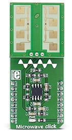
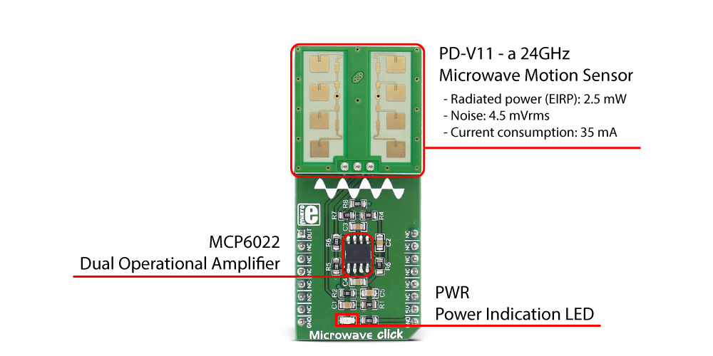
What's on the Microwave click
How the Microwave click works
Microwave click detects movement of objects utilizing Doppler effect. When the PD-V11 microwave sensor is powered on, it starts transmitting radio waves of fixed frequency. As the waves hit a moving object they are reflected back toward PD-V11 microwave motion sensor, with their frequency changed, depending on speed and direction of object's movement.
The Doppler effect - a change in frequency of a wave for the observer and object move closer or further apart from one another. A typical example of the Doppler effect is when a vehicle with siren passes and you hear the pitch drop of the siren.
The PD-V11 microwave motion sensor low power consumption, low noise, and a low wireless power output. See the datasheet to learn more.
The PD-V11 microwave motion sensor picks up reflected waves and converts them to a voltage signal. This signal has the magnitude of several hundred microvolts, so it's sent to the MCP6022 which amplifies the signal, in order to make it readable over the Analog pin on the mikroBUS???. This signal is amplified up to 3.3V.
Once amplified, the signal is routed to the Analog pin (OUT) on the mikroBUS??? line. The proximity of the object can be determined by measuring the amplitude of this signal, and speed/direction by determining its frequency.
The range at which Microwave click can detect movement depends on the way the algorithm is written (see the Software Support section).
Specifications
Type
Motion
Key Features
Frequency: 24GHz;
Radiated power (EIRP): 2.5mW;
noise: 4.5 mVrms;
current consumption: 35 mA;
Interface
Analog
Input Voltage
5V
Click board size
L (57.15 x 25.4 mm)
Pinout diagram
This table shows how the pinout on Microwave click corresponds to the pinout on the mikroBUS socket (the latter shown in the two middle columns).
Notes
Pin
Pin
Notes
Amplified sensed signal output
OUT
1
AN
PWM
16
NC
NC
2
RST
INT
15
NC
NC
3
CS
TX
14
NC
NC
4
SCK
RX
13
NC
NC
5
MISO
SCL
12
NC
NC
6
MOSI
SDA
11
NC
NC
7
3.3V
5V
10
+5V
Power supply
Ground
GND
8
GND
GND
9
GND
Ground
Onboard settings and indicators
Label
Name
Default
Description
PWR
Power
-
Power LED, lights green when the power supply is established properly.
Software Support
We provide a demo application for the Microwave click on LibStock, as well as a demo application (example), developed using MikroElektronika compilers. The demo application can run on all the main MikroElektronika development boards with minimal change to the code depending on the microcontroller used.
Examples Description
The application is composed of three sections :
System Initialization - GPIO, UART, and MCU ADC module initialization
Application Initialization - Measurement of initial reference ADC value used for comparison and movement calculation
Calculation of difference between taken samples and reference ADC value
Reports movement if difference is greater than threshold value
voidapplicationTask(){chartxt[50];uint16_tcounter=0;uint16_tsingle=0;uint16_tsampler=0;uint32_tsum=0;uint16_tdetector=0;// SAMPLINGfor(sampler=0;sampler<_SAMPLES_COUNT;sampler++){single=ADC1_Get_Sample(8);if(single<reference){sum+=single;counter++;}}LATD=0x00;// Turn off D port before next measurement// CALCULATIONif(0!=counter){detector=sum/counter;// REPORTINGif((detector+_THRESHOLD)<reference){WordToStr(detector,txt);UART2_Write_Text("rnMOVE ");UART2_Write_Text(txt);LATD=0xFF;// Turn on D port to report movementDelay_1ms();}}}
The threshold value and number of samples taken per sequence can be easy adjusted by changing the _SAMPLES_COUNT and _THRESHOLD constants.
Setting the samples count to values greater than 500 may slow down your application. The optimal value for this kind of application is 100.
The optimal threshold value depends on the resolution of the MCU's internal ADC module. A small threshold will make the application more sensitive and extend the range of the detection.
This example demonstrates how the click board can detect human movement up to 1,5m.
Note that this is a simple demonstration - a more accurate movement detection requires real digital signal processing. The board used for this demo must be still during the initialization process (power on).
The full application code, and ready to use projects can be found on LibStock.
Other mikroE Libraries used in the example:
UART
Conversions
Additional notes and information
Depending on the development board you are using, you may need USB UART click, USB UART 2 click or RS232 click to connect to your PC, for development systems with no UART to USB interface available on the board. The terminal available in all Mikroelektronika compilers, or any other terminal application of your choice, can be used to read the message.


.jpg)