Cap Extend 4 click provides a unique opportunity to control digital devices by using a variety of physical objects. This click adds touch/proximity detection feature to any application, providing an easy and intuitive framework for building a human-machine interface. The click can be connected to eight different sensors, which can sense touch/proximity through a number of various materials, such as wood, plastic or even metal, thanks to Microchip's proprietary Metal over Capacitive technology.
Cap Extend 4 click can be used for building human-machine interfaces for various touch activated applications, such as light switches, toys and office equipment, device activation via the PCB touch buttons, and other innovative and interesting ways of touch control.
How does it work?
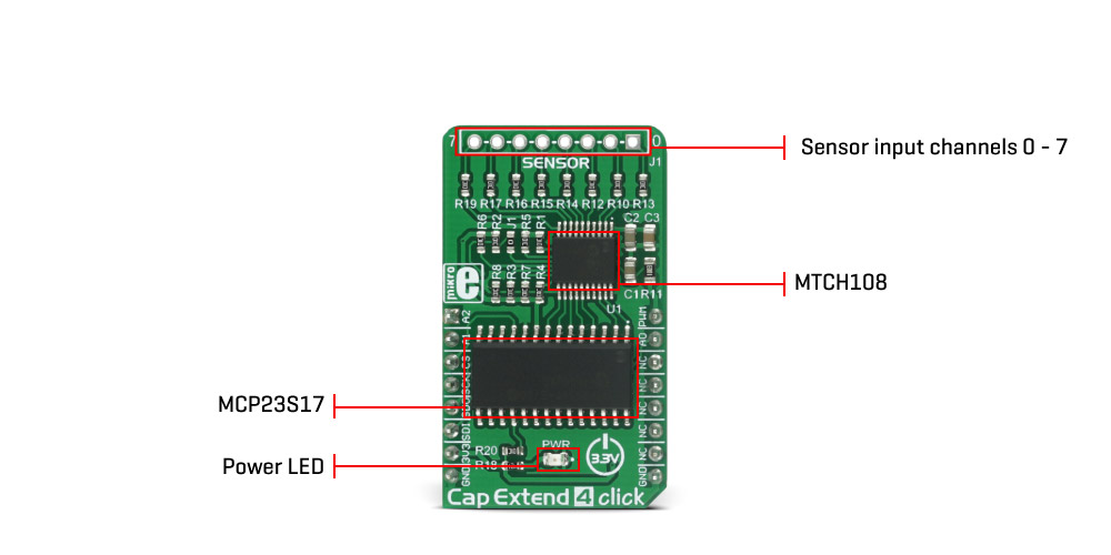
The integrated circuit used to sense touch/proximity is MTCH108, an eight-channel proximity/touch controller from Microchip, featuring their proprietary Metal over Capacitive technology. This device implements capacitive sensors with active guarding capability. It also uses an advanced optimization algorithm to actively suppress noise from the signal to achieve reliable detection.
This device has 8 sensor inputs, ranging from MTI0 to MTI7, and 8 outputs, ranging from MTO0 to MTO7. These outputs are in an open-drain configuration and are set to a LOW logic state if an input event is detected. The outputs are equipped with the pull-up resistors so, in absence of an input event, the pins are pulled to a HIGH logic level.
MTSA pin is used to set the sensitivity of the touch/proximity sensors. As the voltage on this pin is raising, the sensor sensitivity gets lower. This pin can be controlled with the PWM signal at the mikroBUS™ socket, additionally filtered by the 1µF capacitor, providing a constant voltage source for the MTSA pin. Depending on the PWM duty cycle, continuous voltage change is achieved on the MTSA pin.
MTCH108 also features the guard function. This function can be enabled by connecting the GC pin to the GND. The GC pin is multiplexed with the MTO2 pin. If GC/MTO2 pin is left floating, MTI2/GUARD pin will have a regular sensor input functionality and will act as an MTI2 pin. If GC is set to the GND, it will set the MTI2/GUARD pin into the GUARD mode, which can be used to absorb the surrounding noise around the sensors. A small SMD jumper onboard, labeled as JP1 can be unsoldered, leaving the GC/MTO2 pin floating, if needed, but this pin can also be manipulated by the port extender IC so the SMD jumper is populated by default.
This pin, along with all the other sensor outputs is routed to the port B of the MCP23S17, a 16-Bit I/O expander from Microchip. This IC has two 8bit ports of which one is connected to the MTCH108 outputs. The I/O expander IC can use SPI to set the state of the ports, as well as read and write to them. It is used to interface the MTCH108 with the MCU so that the sensor events can be read via SPI interface.
A0 to A2 pins from the MCP23S17 I/O expander are routed to the mikroBUS™, so the proper address can be set by the INT, RST and AN pins of the mikroBUS™. The MCP23S17 I/O has the ability to set its pins as inputs, outputs, can change the polarity of the signal and has many more features regarding the I/O port operations.
The MCP23S17 datasheet holds all the additional information about the register values and their roles. MikroElektronika provides libraries that allow for an easy and trouble-free reading of the sensors, without worrying if the I/O expander registers are set correctly. As always, you can use the provided demo application as a reference for your own project development.
Specifications
Type
Proximity
Applications
It can be used for building human-machine interfaces for various touch activated applications, such as light switches, toys and office equipment, device activation via the PCB touch buttons, and other innovative and interesting ways of touch control.
On-board modules
MTCH108 - 8-Channel Proximity/Touch Controller, MCP23S17 – 16 bit I/O expander interface with SPI
Interface
GPIO,PWM,SPI
Input Voltage
3.3V
Click board size
M (42.9 x 25.4 mm)
Pinout diagram
This table shows how the pinout on Cap Extend 4 click corresponds to the pinout on the mikroBUS™ socket (the latter shown in the two middle columns).
Notes
Pin
Pin
Notes
Hardware Address 2
A2
1
AN
PWM
16
PWM
PWM Output
Hardware Address 1
A1
2
RST
INT
15
A0
Hardware address 0
SPI Chip Select
CS
3
CS
RX
14
NC
SPI Clock
SCK
4
SCK
TX
13
NC
SPI Data Out
SDO
5
MISO
SCL
12
NC
SPI Data In
SDI
6
MOSI
SDA
11
NC
Power Supply
+3.3V
7
3.3V
5V
10
NC
Ground
GND
8
GND
GND
9
GND
Ground
Onboard settings and indicators
Label
Name
Default
Description
LD1
PWR
-
Power LED indicator
J1
SENSOR
Connector for external touch sensors
Software support
We provide a library for Cap Extend 4 click on our LibStock page, as well as a demo application (example), developed using MikroElektronika compilers and mikroSDK. The provided click library is mikroSDK standard compliant. The demo application can run on all the main MikroElektronika development boards.
Library description
Library __capext4_driver declares register address as global variables, sets configuration registers and mikroBUS output pins on expected values, and defines functions to writing in registers and reading from registers.
Key functions:
void capext4_writeReg(uint8_t device_address, uint8_t register_address, uint8_t transfer_data);- This function writes in register 8-bit data
uint8_t capext4_readReg(uint8_t device_address, uint8_t register_address); - This function reads from a register and returns 8-bit value as result.
Example description
System Initialization - Initializes pins, SPI peripheral and logger.
Application Task - Detects presence on all the sensors, and outputs data when change is detected.
voidapplicationTask()
{
uint8_t intcap;
if(_CAPEXT4_CONTROL ==0x00)
{
//Compares all input pins with default value (DEFAULT_VALUE = 0x00)
capext4_writeReg(_CAPEXT4_ADDRESS_DEVICE, _CAPEXT4_INTERRUPT_CONTROL, 0xFF);
//Enables interrupt-on-change
capext4_writeReg(_CAPEXT4_ADDRESS_DEVICE, _CAPEXT4_INTERRUPT_ENABLE, 0xFF);
//Checks is interrupt happeningif(capext4_readReg(_CAPEXT4_ADDRESS_DEVICE, _CAPEXT4_INTERRUPT_FLAG) ==0x00)
{
//Reads value on input, it causes that interrupt will stop
intcap = capext4_readReg(_CAPEXT4_ADDRESS_DEVICE, _CAPEXT4_INTERRUPT_CAPTURE);
//Writes on UART if interrupt is not happening, all input pins are 0
mikrobus_logWrite("No presence detected.", _LOG_LINE);
}
//Disables interrupt-on-change
capext4_writeReg(_CAPEXT4_ADDRESS_DEVICE, _CAPEXT4_INTERRUPT_ENABLE, 0x00);
_CAPEXT4_CONTROL =0x01;
}
//Compares all input pins with previous value
capext4_writeReg(_CAPEXT4_ADDRESS_DEVICE, _CAPEXT4_INTERRUPT_CONTROL, 0x00);
//Enables interrupt-on-change
capext4_writeReg(_CAPEXT4_ADDRESS_DEVICE, _CAPEXT4_INTERRUPT_ENABLE, 0xFF);
//Checks is interrupt happeningif(capext4_readReg(_CAPEXT4_ADDRESS_DEVICE, _CAPEXT4_INTERRUPT_FLAG))
{
//Eeads value on input when interrupt is happening
intcap = capext4_readReg(_CAPEXT4_ADDRESS_DEVICE, _CAPEXT4_INTERRUPT_CAPTURE);
writeResult(intcap);
_CAPEXT4_CONTROL =0x00;
}
//Disables interrupt-on-change
capext4_writeReg(_CAPEXT4_ADDRESS_DEVICE, _CAPEXT4_INTERRUPT_ENABLE, 0x00);
Delay_ms(1000);
}
The full application code, and ready to use projects can be found on our LibStock page.
Other MikroElektronika Libraries used in the example:
UART
Conversions
C_String
Additional notes and information
Depending on the development board you are using, you may need USB UART click, USB UART 2 click or RS232 click to connect to your PC, for development systems with no UART to USB interface available on the board. The terminal available in all MikroElektronika compilers, or any other terminal application of your choice, can be used to read the message.
mikroSDK
This click board is supported with mikroSDK - MikroElektronika Software Development Kit. To ensure proper operation of mikroSDK compliant click board demo applications, mikroSDK should be downloaded from the LibStock and installed for the compiler you are using.
For more information about mikroSDK, visit the official page.