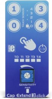
Cap Extend 3 click features four capacitive sensor pads integrated on the PCB, that can sense touch through a variety of different materials. This click can sense touch through plastic, wood, or even metal, thanks to the proprietary Metal over Capacitive technology. All these materials can be used to protect the surface of the PCB and sensor pad traces, allowing implementation of all kinds of human-machine interfaces and seamless integration of the touch-sensitive buttons into various kinds of front panels. The click also features a connector used for connecting to external sensors.
Features like the multi-stage active noise suppression filtering, automatic environmental compensation, high signal-to-noise ratio (SNR) and support for a wide range of sensor pad shapes and sizes, allow this device to be used as a reliable replacement for buttons or switches in many applications, including light switches, office equipment and toys, display and keypad backlight activation, and similar applications where a reliable and aesthetically pleasing button alternative is required.
How does it work?
Cap Extend 3 click features the MTCH105, a five-channel proximity/touch controller with active guarding capability, from Microchip. The MTCH105 IC uses a sophisticated scan optimization algorithm to actively attenuate noise from the signal. Having a good SNR is one of the essential prerequisites when implementing a reliable capacitive touch detection. Good SNR coupled with the automatic environmental compensation, low power consumption and simple I/O interface make this IC a perfect solution for building the Cap Extend 3 click with four reliable touchpad sensors.
The surface of Cap Extend 3 click is protected with the acrylic glass. If a touch event is detected on one of the sensors connected to input pins of the IC (MTI0 to MTI4), the state of the corresponding channel output pin, (MTO0 to MTO4) will be pulled to a logic LOW level, indicating that the channel has been activated - touch has been detected on that specific channel. This will also be indicated by a LED, related to the activated channel. The output pins are working in an open drain configuration, thus are pulled HIGH by the onboard resistors.
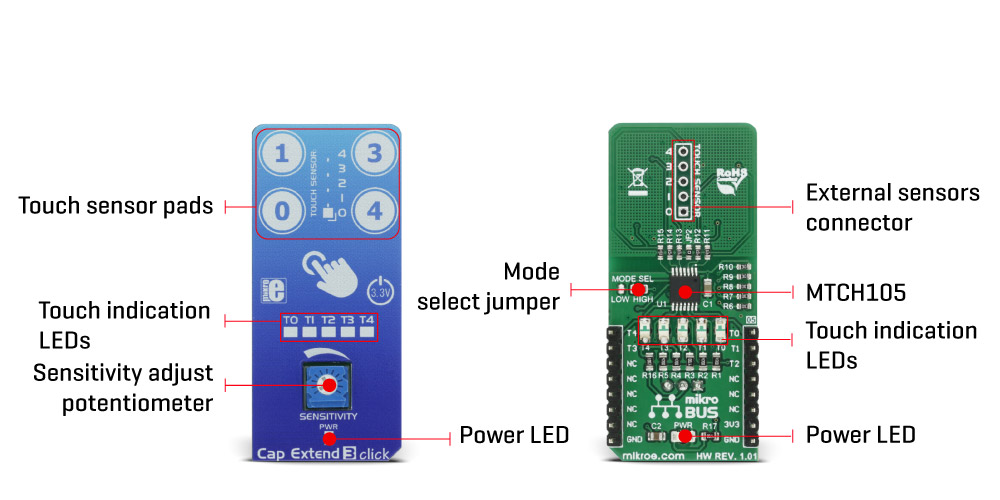
Although the IC has five channels, only four buttons are implemented, as one of the channels is multiplexed with the active guard functionality. Guard control (GC) pin is multiplexed with the MTO2 pin, while GUARD pin is multiplexed with the MTI2 pin. If the GC pin is pulled down to a GND level, it will set the MTI2/GUARD pin into the GUARD mode, which can be used to absorb the noise around the sensor pads. A PCB trace connected to this pin surrounds all the sensor pads, providing active guarding and enhancing the SNR significantly. It should be noted that when the Active Guard is activated, a LED on the MTO2 pin will be lit, indicating that the Guard function is enabled.
A small onboard SMD jumper, labeled as JP2 can be left unpopulated, disconnecting the guard pin from the network of PCB traces that surround the sensor pads. This option is useful when the external sensor pads are used, or when the active guard function is not required so that the MTI2/MTO2 can be used as additional external cap touch sensor.
Cap Extend 3 click also allows connecting of external sensors through the connector labeled as J1. The MTCH105 itself allows sensors of various sizes and shapes to be used, as well as sensors made of several different materials - carbon printing on plastic film, Indium Tin Oxide (ITO) pad, wire/cable, etc. External sensors connector allows expanding touch capabilities of the Cap Extend 3 beyond the click itself. All five channels are routed to this connector, so users can decide on their preferred configuration of sensors and decide if the active guard feature will be used or replaced by another sensor.
The sensitivity of the sensor pads can be adjusted via the onboard potentiometer, connected between the VCC and GND. The potentiometer acts as a voltage divider, with its wiper connected to the MTSA pin of the MTCH105. Raising the voltage level of this pin will result in the lower sensitivity of the MTCH105 inputs.
The onboard SMD jumper labeled as the MODE SEL is used to select the working mode of the device. The device can work in either normal or the low power mode. While working in normal mode, the burst scan of the inputs will happen continuously, providing the shortest detection time. When set to work in the low power mode, the device will have a delay of 256ms between each burst scan interval. It will allow for significantly reduced power consumption, but the touch detection can be longer in this case. The device will work in a normal mode, when the MTPM pin is set to the VCC level, by switching the MODE SEL jumper to the position labeled as HIGH. When the MODE SEL jumper is set to the position labeled as LOW, the MTPM pin will be set to the GND level and the device will work in the low power mode.
The device also features a timeout reset. This function is useful when the sensor pad is obstructed by a foreign object, or its state is otherwise stuck as activated. When the channel stays activated for longer than 10 seconds, the corresponding channel will be reset and recalibrated.
All the five channel output pins of the MTCH105 are routed to the mikroBUS™ so that their states can be read and detected by the MCU in an easy and simple way. The channels are routed to the AN, PWM, INT, RST and CS pins of the mikroBUS™.
Specifications
| Type |
Proximity |
| Applications |
It can be used as a reliable replacement for buttons or switches in many applications, including light switches, office equipment and toys, display and keypad backlight activation, and similar. |
| On-board modules |
MTCH105, a 5-Channel Proximity/Touch Controller from Microchip |
| Key Features |
The device features multi-stage active noise suppression filtering, automatic environmental compensation, high signal-to-noise ratio (SNR) and it can sense touch through many different materials, including metal panels. |
| Interface |
GPIO |
| Input Voltage |
3.3V |
| Click board size |
L (57.15 x 25.4 mm) |
Pinout diagram
This table shows how the pinout on Cap Extend 3 click corresponds to the pinout on the mikroBUS™ socket (the latter shown in the two middle columns).
| Notes | Pin |  | Pin | Notes |
|---|
| Sensor 0 state |
TO0 |
1 |
AN |
PWM |
16 |
TO3 |
Sensor 3 state |
| Sensor 1 state |
TO1 |
2 |
RST |
INT |
15 |
TO4 |
Sensor 4 state |
| Sensor 2 state |
TO2 |
3 |
CS |
RX |
14 |
NC |
|
|
NC |
4 |
SCK |
TX |
13 |
NC |
|
|
NC |
5 |
MISO |
SCL |
12 |
NC |
|
|
NC |
6 |
MOSI |
SDA |
11 |
NC |
|
| Power supply |
+3.3V |
7 |
3.3V |
5V |
10 |
NC |
|
| Ground |
GND |
8 |
GND |
GND |
9 |
GND |
Ground |
Onboard settings and indicators
| Label | Name | Default | Description |
|---|
| LD1 |
TO0 |
- |
Sensor 0 state indicator
|
| LD2 |
TO1 |
- |
Sensor 1 state indicator |
| LD3 |
TO2 |
- |
Sensor 2 state indicator |
| LD4 |
TO3 |
- |
Sensor 3 state indicator |
| LD5 |
TO4 |
- |
Sensor 4 state indicator |
| LD6 |
PWR |
- |
Power LED indicator |
| JP1 |
MODE SEL |
Right |
Mode selection, left (LOW) - low power mode, right (HIGH) - normal power mode |
| JP2 |
JP2 |
Populated |
Jumper used to connect the guard pin to the traces network that surrounds sensor pads |
| J1 |
TOUCH SENSOR |
|
1x5 header used for connecting sensor pads |
Software support
We provide a library for Cap Extend 3 click on our LibStock page, as well as a demo application (example), developed using MikroElektronika compilers and mikroSDK. The provided click library is mikroSDK standard compliant. The demo application can run on all the main MikroElektronika development boards.
Library Description
Initializes GPIO driver and click driver functions, which detect a touch on determined pins. For more details, check the documentation.
Key functions
uint8_t capextend3_Touch_0()- The function reads a state of the AN pin.
uint8_t capextend3_Touch_1()- The function reads a state of the RST pin.
uint8_t capextend3_Touch_2()- The function reads a state of the CS pin.
uint8_t capextend3_Touch_3()- The function reads a state of the INT pin.
uint8_t capextend3_Touch_4()- The function reads a state of the PWM pin.
Examples Description
The demo application is composed of three sections:
- System Initialization - Initializes AN, RST, CS, PWM, INT pin as INPUT.
- Application Initialization - Initializes GPIO Driver.
- Application Task - (code snippet) - The USB UART shows the number of the button which is being touched.
void applicationTask()
{
   touch_1 = capextend3_Touch_1();
   touch_0 = capextend3_Touch_0();
   touch_3 = capextend3_Touch_3();
   touch_4 = capextend3_Touch_4();

   if( touch_0 == 0 )
      mikrobus_logWrite("Touch 0 ",_LOG_LINE);

   if( touch_1 == 0 )
      mikrobus_logWrite("Touch 1 ",_LOG_LINE);

   if( touch_3 == 0 )
      mikrobus_logWrite("Touch 3 ",_LOG_LINE);

   if( touch_4 == 0 )
      mikrobus_logWrite("Touch 4 ",_LOG_LINE);

   Delay_ms( 100 );
}
The full application code, and ready to use projects can be found on our LibStock page.
Other MikroElektronika libraries used in the example:
Additional notes and information
Depending on the development board you are using, you may need USB UART click, USB UART 2 click or RS232 click to connect to your PC, for development systems with no UART to USB interface available on the board. The terminal available in all MikroElektronika compilers, or any other terminal application of your choice, can be used to read the message.
mikroSDK
This click board is supported with mikroSDK - MikroElektronika Software Development Kit. To ensure proper operation of mikroSDK compliant click board demo applications, mikroSDK should be downloaded from the LibStock and installed for the compiler you are using.
For more information about mikroSDK, visit the official page.