The PWM control signal section itself is built around PCA9685, an integrated 12-bit, 16-channel PWM driver, which can be configured to either sink 25mA per channel or drive each channel sourcing up to 10mA. Each channel can have its duty cycle independently set from 0% to 100%. Driven by the I2C interface, it is really easy to operate. Offering 16 independent channels, each with its own PWM duty cycle and current sensing ability, this Click board™ represents a powerful servo controller, especially usable when a big number of servos needs to be controlled in a simple and easy way, such as in the movie or theater industry (animatronics), robotics, RC toys and similar
How does it work?
A common servo is typically controlled by a PWM signal with the variable duty cycle. The width of the pulse determines the position of the arm. The signal frequency can vary from 50Hz, up to 200Hz and more, depending on the model of the servo. The arm is moved by a small DC motor, with the help of gears with different transmission ratios. The arm is also internally connected to a small potentiometer, which provides a position feedback to the internal servo electronic circuitry. A typical servo does not provide any feedback to the external controller, so the controller has to assume that the arm of the servo is always at the given position.
Servo click uses PCA9685, an integrated 12-bit, 16-channel PWM driver from NXP. This driver contains 12-bit fixed frequency PWM generator for each channel, clocked by the internal 25MHz clock generator. The output signal frequency is determined by the prescaler value, which is written to the appropriate register. The output channels can be set either in the open drain or in the push-pull configuration. In the first case, they will be able to sink up to 25mA from up to 5.5V power supply, while in the second case, they will be able to both drive with up to 10mA or sink up to 25mA. This is more than enough to control the servo, which typically works with 4.8V signals at its PWM input. The PCA9685 device is originally designed as the LED driver, but the relatively low PWM frequency and limited current capabilities of its outputs make it a better choice as a servo controller. In fact, it is more than perfectly suited to drive servo arrays, due to its compact size and number of channels, which can be expanded even further, by simply changing the I2C slave address of each device. PWM channels are easily driven via the I2C interface. The device also offers Output Enable pin, routed to the mikroBUS™ CS pin, labeled as the OE. A LOW logic level on this pin will set all the outputs to the predefined logic state, turning the PWM generators OFF. This may either leave the servo into the fixed position or turn it down completely, allowing it to free spin - depending on the servo model.
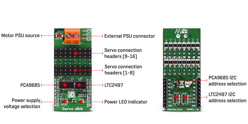
The servo can be connected to any of the sixteen headers. Each header has three pins, two of which provide power, and third pin which is routed to the PCA9685, carrying PWM control signal. The power source for the servo DC motors can be selected between the mikroBUS™ 5V and the external connector. The external connector can provide more power for servos that operate with heavier loads, therefore if using a large number of smaller servos or servos that demand more current, the SMD jumper labeled as VCC MOT should be at the EXT position. In this case, an external PSU which can provide more current can be used.
If there is a force attempting to move the servo arm in one direction while it is set to a certain position, the servo will oppose to this force by draining more current from the power supply. Also, the current exponentially drops as the servo DC motor accelerates, so this can be utilized to sense an obstacle and correct the servo position accordingly. So, the servo current consumption can provide a form of feedback, that can be used in the software. Therefore, each header is equipped with a shunt resistor, which introduces a small voltage drop across the connected servo. This voltage drop is captured and converted by the LTC2497, a 16-Bit, 16-channel delta-sigma ADC, with easy drive input current cancellation and I2C Interface, by Analog Devices (former Linear Technology). The ADC uses an accurate reference of 2.048V provided by a small onboard reference voltage regulator. An extremely low noise of this ADC IC and patented sampling scheme, coupled with the low reference voltage, allow very small voltage drops across the shunt resistor to be accurately converted.
The Click board™ can operate with both 3.3V and 5V MCUs. The operating voltage can be selected by an onboard SMD jumper, labeled as the VCC SEL. There are two more SMD jumpers, labeled as the PWM and ADC, located at the bottom of the Click board™. These jumpers allow selection of the slave I2C address for each of the two onboard ICs. This way, several Servo clicks can be stacked, allowing control and driving of a large servo array. However, in such scenario, servos can pull a lot of current, so a special care should be taken not to overload the power supply and the Servo click connectors. Maximum current per servo channel is about 2A, but combined current from 16 servos should stay below 3.0 A
Specifications
| Type |
Motion |
| Applications |
Servo click is especially usable when a big number of servos needs to be controlled in a simple and easy way, such as in the movie or theater industry (animatronics), robotics, RC toys and similar applications |
| On-board modules |
PCA9685, an integrated 12-bit, 16-channel PWM driver from NXP; LTC2497, a 16-Bit, 16-channel delta-sigma ADC, with easy drive input current cancellation and I2C Interface, by Analog Devices |
| Key Features |
An accurate 12-bit PWM control signal on 16 different servo channels, with programmable frequency. Additional sense resistor on each channel allows current readings for each channel, offering extended servo feedback with no modifications of the actual servo |
| Interface |
GPIO,I2C |
| Input Voltage |
3.3V or 5V |
| Click board size |
L (57.15 x 25.4 mm) |
Pinout diagram
This table shows how the pinout on Servo click corresponds to the pinout on the mikroBUS™ socket (the latter shown in the two middle columns).
| Notes | Pin |  | Pin | Notes |
|---|
|
NC |
1 |
AN |
PWM |
16 |
NC |
|
|
NC |
2 |
RST |
INT |
15 |
NC |
|
| Output Enable |
OE |
3 |
CS |
RX |
14 |
NC |
|
|
NC |
4 |
SCK |
TX |
13 |
NC |
|
|
NC |
5 |
MISO |
SCL |
12 |
SCL |
I2C Clock |
|
NC |
6 |
MOSI |
SDA |
11 |
SDA |
I2C Data |
| Power supply |
3.3V |
7 |
3.3V |
5V |
10 |
5V |
Power supply |
| Ground |
GND |
8 |
GND |
GND |
9 |
GND |
Ground |
Onboard settings and indicators
| Label | Name | Default | Description |
|---|
| PWR |
PWR |
- |
Power LED indicator |
| VCC MOT |
VCC MOT |
Left |
Motor PSU source selection: left position external PSU, right position 5V from |
| VCC SEL |
VCC SEL |
Left |
Logic voltage level selection: left position 3.3V, right position 5V |
| 1 - 16 |
1 - 16 |
- |
Servo motor connection headers (channels 1 to 16) |
Software support
We provide a demo application for Servo click on our Libstock page, as well as a demo application (example), developed using MikroElektronika compilers. The demo can run on all the main MikroElektronika development boards.
Library Description
This library will allow you to control multiple servo motors at once.
Key functions:
void servo_init(uint8_t minPosition, uint8_t maxPosition, uint16_t lowResolution, uint16_t highResolution); - Main click board initialization routine.void servo_setMode(uint8_t mode,uint8_t _data); - Set's the operation mode of the click board.servo_sleep(); - The function needs to be set before setting the frequency.void servo_setFREQ(uint16_t freq); - Used for setting the frequency.void servo_setPosition(uint8_t motor, uint8_t position); - Set the position of the selected servo motor.
Example description
The application is composed of three sections:
- System Initialization - Initializes the I2C module and the CS pin as the output
- Application Initialization - Initializes the driver and the servo (setting the minimum and maximum servo motors position and resolutions). Default resolution is 1ms. The IC is set to Sleep mode in order to set the frequency, after which the working mode of the servo is set
- Application Task - (code snippet) - The servo motor is moved across three different positions: 0, 90, 180 - every two seconds. The current consumption is sampled while the servo transitions between these points
void applicationTask()
{
 servo_setPosition(_SERVO_MOTOR_1, 0);
 Delay_ms( 2000 );
 servo_setPosition(_SERVO_MOTOR_1, 90);
 Delay_ms( 1000 );
 servo_setPosition(_SERVO_MOTOR_1, 180);
 Delay_ms( 2000 );
 servo_setPosition(_SERVO_MOTOR_1, 90);

 Current = setvo_getCurrent(_SERVO_POSITIVE_CH0);
 IntToStr(Current , text);
 mikrobus_logWrite( "Current - ", _LOG_TEXT );
 mikrobus_logWrite( text, _LOG_TEXT );
 mikrobus_logWrite( " mA", _LOG_LINE );

 Delay_ms( 1000 );
}
The full application code, and ready to use projects can be found on our Libstock page.
Other MikroElektronika libraries used in the example:
- I2C Library
- UART Library
- Conversions Library
- C_String Library
Additional notes and information
Depending on the development board you are using, you may need USB UART click, USB UART 2 click or RS232 click to connect to your PC, for development systems with no UART to USB interface available on the board. The terminal available in all MikroElektronika compilers, or any other terminal application of your choice, can be used to read the message.
mikroSDK
This click board is supported with mikroSDK - MikroElektronika Software Development Kit. To ensure proper operation of mikroSDK compliant click board demo applications, mikroSDK should be downloaded from the LibStock and installed for the compiler you are using. For more information about mikroSDK, visit the official page.