How does it work?
The TMR Angle click contains the TLE5501 from Infineon Technologies AG – analog TMR-based angle sensors for any kind of angular position sensing from Infineon, and the MCP3204, a converter with SPI serial interface from Microchip. Regarding the TLE5501, the application fields range from steering angle applications with the highest functional safety requirements to motors for wipers, pumps and actuators and electric motors in general. TLE5501 is dedicated to any automotive but also industrial and consumer applications like robotics or gimbal.

Some of its key features include large output signals of up to 0.37 V/V for easy analog value readout, discrete bridge with differential sine and cosine output, a very low supply current < 2.5 mA, a magnetic field range 20 mT to 100 mT and a Typ. angle error < 1.0° (over the whole temperature and lifetime profile). It has been primarily designed for safety.
One major benefit of the Infineon TMR technology is its high sensing sensitivity coming with a high output voltage. So unlike other technologies, a TMR based sensor does not require any additional internal amplifier. Thus the sensor can be connected directly to the microcontroller without any further amplification – saving costs for the end customer. There is yet another cost saving aspect of Infineon's TMR technology. TMR shows a very low temperature drift reducing external calibration and compensation efforts. In addition, the TMR technology is also well known for its low current consumption.
When it comes to reading the output analog value, the MCP3204 is used – a 4-Channel A/D converter with SPI serial interface, from Microchip, it is ideally suited for sensor interface, process control, data acquisition and battery operated systems. It has a 12-bit resolution, and it is programmable to provide two pseudo-differential input pairs or four single-ended inputs. Configuration is done as part of the serial command before each conversion begins. When used in the pseudodifferential mode, each channel pair (i.e., CH0 and CH1, CH2 and CH3 etc.) On this Click board™ the output sin and cos signals are wired as a pseudo-differential input signals to the MCP3204.
Communication with the devices is accomplished using a simple serial interface compatible with the SPI protocol. The devices are capable of conversion rates of up to 100 ksps. The MCP3204/3208 devices operate over a broad voltage range (2.7V - 5.5V).
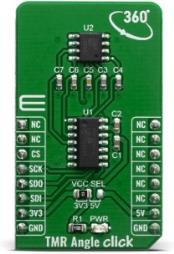
The TMR Angle Click board™ offers a selection between 3.3V and 5V operation, with the onboard SMD jumper, labeled as PWR SEL. This allows both 3.3V and 5V MCUs to be interfaced with this Click board™.
Specifications
| Type |
Magnetic |
| Applications |
The application fields range from steering angle applications with the highest functional safety requirements to motors for wipers, pumps and actuators and electric motors in general. |
| On-board modules |
TLE5501, magnetic sensor from Infineon and MCP3204, a converter with SPI serial interface from Microchip |
| Key Features |
large output signals for easy analog value readout, discrete bridge with differential sine and cosine output, a very low supply current 2.5 mA, a magnetic field range 20 mT to 100 mT |
| Interface |
SPI |
| Compatibility |
mikroBUS |
| Click board size |
M (42.9 x 25.4 mm) |
| Input Voltage |
3.3V or 5V |
Pinout diagram
This table shows how the pinout on TMR Angle click corresponds to the pinout on the mikroBUS™ socket (the latter shown in the two middle columns).
| Notes |
Pin |
 |
Pin |
Notes |
|---|
| |
NC |
1 |
AN |
PWM |
16 |
NC |
|
| |
NC |
2 |
RST |
INT |
15 |
NC |
|
| Chip Select |
CS |
3 |
CS |
RX |
14 |
NC |
|
| SPI Clock |
SCK |
4 |
SCK |
TX |
13 |
NC |
|
| SPI Data Out |
SDO |
5 |
MISO |
SCL |
12 |
NC |
|
| SPI Data Out |
SDI |
6 |
MOSI |
SDA |
11 |
NC |
|
| Power Supply |
3.3V |
7 |
3.3V |
5V |
10 |
5V |
Power Supply |
| Ground |
GND |
8 |
GND |
GND |
9 |
GND |
Ground |
Onboard settings and indicators
| Label |
Name |
Default |
Description |
|---|
| LD1 |
PWR |
- |
Power LED Indicator |
Software Support
We provide a library for the TMR Angle Click on our LibStock page, as well as a demo application (example), developed using MikroElektronika compilers. The demo can run on all the main MikroElektronika development boards.
Library Description
The library covers all the necessary functions to control TMR Angle click board. A library performs a standard SPI interface communication.
Key functions:
void tmrangle_initSensorData() - Read and stores parameters data function.void tmrangle_calibrationFindParam( tmrangle_calib_data_t *calibParam ) - Get new calibration rotation parameters function.float tmrangle_getCalibAngle( tmrangle_calib_data_t *calibParam ) - Calculate the calibrated angle ( degree ) function.
Examples description
The application is composed of three sections :
- System Initialization - Initializes SPI and start to write log.
- Application Initialization - Initialization driver enables - SPI, initializes, also write log.
- Application Task - (code snippet) This is a example which demonstrates the use of TMR Angle Click board. Reads angle value in degrees. Results are being sent to the Usart Terminal where you can track their changes. All data logs write on usb uart changes for every 1 sec.
void applicationTask()
{
    tmrangle_initSensorData();
    tmrangle_initCalibData( &calibrationStoreParams, _TMRANGLE_MAX_DIFF_SIN, _TMRANGLE_MAX_DIFF_COS, _TMRANGLE_MIN_DIFF_SIN, _TMRANGLE_MIN_DIFF_COS, _TMRANGLE_SIN_45, _TMRANGLE_COS_45, _TMRANGLE_SIN_135, _TMRANGLE_COS_135 );
    tmrangle_calibrationFindParam( &calibrationStoreParams );

    angle = tmrangle_getCalibAngle( &calibrationStoreParams );

    FloatToStr( angle, logText );
    mikrobus_logWrite( " Angle is ", _LOG_TEXT );
    mikrobus_logWrite( logText, _LOG_TEXT );
    mikrobus_logWrite( degCel, _LOG_LINE );
    mikrobus_logWrite( "----------------------", _LOG_LINE );

    Delay_1sec();
}
The full application code, and ready to use projects can be found on our LibStock page.
Other mikroE Libraries used in the example:
Additional notes and informations
Depending on the development board you are using, you may need USB UART click, USB UART 2 click or RS232 click to connect to your PC, for development systems with no UART to USB interface available on the board. The terminal available in all MikroElektronika compilers, or any other terminal application of your choice, can be used to read the message.
mikroSDK
This Click board™ is supported with mikroSDK - MikroElektronika Software Development Kit. To ensure proper operation of mikroSDK compliant Click board™ demo applications, mikroSDK should be downloaded from the LibStock and installed for the compiler you are using.
For more information about mikroSDK, visit the official page.
Resources
Downloads