How does it work?
The Secure SOIC click is designed with support for CryptoAuthentication™ devices from Microchip in mind. These CryptoAuthentication™ devices are equipped with many different features, such as EEPROM array, certificates, consumption logging, security configurations and other types of secure data. Secure SOIC click, supports the SPI, I2C, and SWI communication interfaces with a flexibility that allows use in various security applications, including Network/IoT Node Endpoint Security, Secure Boot, Small Message Encryption, Key Generation for Software Download, Ecosystem control, Anti Counterfeiting and similar.

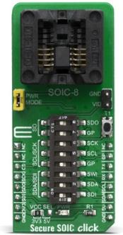
However, the Secure SOIC click is designed in a way that every IC from the CryptoAuthentication™ family from Microchip is fully supported with all of its features. Due to many different ICs and possibilities supported, the only way for achieving such a goal was to use the 8-positions DIP switch. That way, user is able to select the communication lines routed the way it is required for any application.
Three communication protocols are supported: I2C, SPI, and SWI (Single-Wire Interface), simply by selecting the appropriate switches, according to the table on the back of the click board™. Besides that, Secure SOIC click also have the onboard intrusion switch and external power supply solder pads, which is needed when it comes to OTP.
Many ICs from the CryptoAuthentication™ family supports the parasitic power supply. With that in mind, this click board™ also has a power supply mode selection jumper, marked as PWR MODE. When the jumper is removed, the IC is powered only via the data lines (parasitic power supply mode). When the jumper is in its place, normal power operation is being used. The Secure SOIC click has all needed capacitors and the diode, needed for parasitic power supply mode, while the communication lines are pulled high by carefully calculated resistors, to achieve the best results when the parasitic power is used. However, depending on the application and implementation, user might need to change some of these values.
The chips themselves uses a minimal number of pins; However, Secure SOIC Click uses all of the UART (used for SWI communication), I2C, and SPI pins available on the mikroBUS™. That is due to many different ICs, communications, and therefore, combinations and use scenarios.
The voltage range which can be used to power up the Secure SOIC click, allows for it to work with both 3.3V and 5V capable MCUs. It can be selected by soldering a small SMD jumper, labeled as VCC SEL to the correct position.
Specifications
| Type |
Encryption |
| Applications |
Used for developing various applications, such as storage of up to 16 keys, certificates, miscellaneous read/write, read-only or secret data, consumption logging, and security configurations |
| On-board modules |
OTS-8(16)-1.27-03, an universal cocket for 8-pin SOIC packaged integrated |
| Key Features |
Supported I2C, SPI, and the SWI interfaces, parasitic power supply, external voltage supply for OTP, good flexibility. |
| Interface |
I2C,SWI,SPI,GPIO |
| Compatibility |
mikroBUS |
| Click board size |
L (57.15 x 25.4 mm) |
| Input Voltage |
3.3V or 5V |
Pinout diagram
This table shows how the pinout on Secure SOIC click corresponds to the pinout on the mikroBUS™ socket (the latter shown in the two middle columns).
| Notes |
Pin |
 |
Pin |
Notes |
|---|
| |
NC |
1 |
AN |
PWM |
16 |
NC |
|
| |
NC |
2 |
RST |
INT |
15 |
GP |
General Purpose Input/Output |
| Chip Select |
CS |
3 |
CS |
RX |
14 |
TX |
SWI Line |
| SPI Clock |
SCK |
4 |
SCK |
TX |
13 |
RX |
SWI Line |
| SPI Data Out |
SDO |
5 |
MISO |
SCL |
12 |
SCL |
I2C Clock |
| SPI Data In |
SDI |
6 |
MOSI |
SDA |
11 |
SDA |
I2C Data |
| Power Supply |
3.3V |
7 |
3.3V |
5V |
10 |
5V |
Power Supply |
| Ground |
GND |
8 |
GND |
GND |
9 |
GND |
Ground |
Onboard settings and indicators
| Label |
Name |
Default |
Description |
|---|
| LD1 |
PWR LED |
- |
Power LED Indicator |
| JP1 |
VCC SEL |
Left |
Power supply voltage selection, left position 3V3, right position 5V |
| SW1 |
DIP Switch |
- |
I2C / SPI / SWI communication selection switch |
DIP Switch configuration table
| |
S1 |
S2 |
S3 |
S4 |
S5 |
S6 |
S7 |
S8 |
|---|
| SPI |
ON |
OFF |
ON |
OFF |
OFF |
OFF |
OFF |
ON |
|---|
| I2C |
OFF |
ON |
OFF |
ON |
OFF |
OFF |
ON |
OFF |
|---|
| SWI |
OFF |
OFF |
OFF |
OFF |
ON |
ON |
ON |
OFF |
|---|
Software support
We provide libraries for all click boards in the Secure family on our LibStock page, as well as a demo application (example), developed using MikroElektronika compilers. The demo can run on all the main MikroElektronika development boards. However, due to many different ICs compatible with Secure SOIC click, the existing libraries from the other Secure family click boards may be used.
Secure SOIC click comes with the ATSHA204A IC included in the package.
For more information about the individual integrated circuits, features, libraries and examples, visit the desired web page, linked below, depending of the chip being used:
Additional notes and informations
Depending on the development board you are using, you may need USB UART click, USB UART 2 click or RS232 click to connect to your PC, for development systems with no UART to USB interface available on the board. The terminal available in all MikroElektronika compilers, or any other terminal application of your choice, can be used to read the message.
Resources
Downloads