How does it work
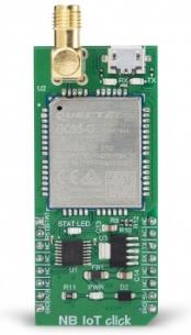
NB IoT click is equipped with the BC95-G module from Quectel Wireless Solutions, which supports LTE NB1 technology, developed with IoT applications in mind. It supports several NB frequency bands: B1, B3, B5, B8, B20, and B28. The module supports point-to-point MO and MT messages, widely used for M2M communication. Packed with the set of protocols that allow data and SMS transfer using the NB1 technology and the ultra-low power consumption makes this module a perfect choice when it comes to building IoT applications.
.jpg)
As mentioned before, BC95-G module is the main component of the click board and it consists of a number of internal blocks or sections, such as the RF Transceiver section, Flash SRAM section, Power Management section, and the cellular baseband processor with the peripheral interfaces. BC95 module supports several peripheral interfaces, including two UART interfaces (including the main UART and debug UART interface), USIM card interface, and GPIO interface.
The main UART interface can be used for the AT command communication and data transmission. It supports baud rates of 9600 bps. The main UART interface can also be used for the firmware upgrade. In that case, a baud rate of 115200 bps is used.
The Quectel BC95 module has to be powered by a clean and stable power supply. The voltage needed for the module to work properly is 4V and it is derived from the 5V mikroBUS™ rail, through the MCP1826, a 1A low drop output (LDO) regulator from Microchip. Although the Quectel BC95 module is an ultra-low power device, its power consumption can briefly peak sometimes, so 1A LDO had to be used.
The BC95 module does not have a dedicated USB interface, therefore a USB-to-UART circuit had to be added to the NB IoT click to provide USB to UART conversion. The FT230X, a highly integrated USB-UART bridge solution from FTDI is used, offering very simple integration thanks to its compact size and a small number of external components required. Two LEDs are used to signalize the data traffic through this IC: the red LED labeled as TX indicates the UART transmission, while the yellow LED labeled as RX indicates the UART reception.
This Click board™ is equipped with the micro USB connector. It allows the module to be powered and configured by a personal computer. Quectel Wireless Solutions Company offers a software suite which can be used to configure the BC95 module. However, the FT230X IC requires drivers in order to work. FTDI offers drivers for all major OSes on their official driver download web page. Also, Windows OS drivers are included in the download section, below.
The micro SIM card holder on the back of the Click board™ is used to install the SIM card. This device cannot be used without a valid SIM card which allows connection to the cellular network.
Digital sections of the BC95 module are supplied with power by an integrated LDO regulator, so it is necessary to convert the logic voltage level of the microcontroller (MCU) communication lines. By utilizing the LDO output (routed through the MOSFET switching circuitry), the needed reference voltage is provided for one side of the TXB0106, a 6bit bi-directional logic voltage level converter. The reference voltage for the other side of the TXB0106 is taken from the 3.3V power rail of the mikroBUS™. The small switching circuitry composed of a few signal-level MOSFETs is used to provide a way to switch off the FT230X when the Click board™ is inserted into the mikroBUS™ socket. This allows uninterrupted communication with the host MCU.
The STAT pin is used to signalize the status of the device. This pin is routed both to the mikroBUS™ AN pin through the TXB0106 level translator, and the yellow LED labeled STAT, which is used to visually indicate the device status. The network status is indicated by the TXD LED, using the following pattern:
- LOW (STAT LED is OFF) - the module is not working or attached to a network
- HIGH (STAT LED is ON) - the module is attached to a network
The module can be reset by pulling the RST pin of the mikroBUS™ pin to a LOW logic level. This pin is pulled up to a HIGH level by an internal pull-up resistor. Besides the hardware reset, the module can also be reset by using the AT command. More information about the available AT commands can be found in the download section, below. However, the Click board™ comes supported by the mikroSDK library. The library contains functions which simplify the software development, integrating several AT commands into a single function call. Using mikroSDK makes the code way more readable, but more importantly - easily portable.
Specifications
| Type |
GSM |
| Applications |
Perfectly suited for smart metering, bike sharing, smart parking, smart city, security and asset tracking, agricultural and environmental monitoring, and more |
| On-board modules |
BC95, an LTE CAT NB1 module, from Quectel; FT230X, a USB to UART IC from FTDI Chip; TXB0106, a 6bit bidirectional level shifter from Texas Instruments |
| Key Features |
Embedded communication stacks, multi-band NB technology support, aimed at M2M and IoT applications, SMA antenna connector, USB to UART connectivity, network status indication, and more |
| Interface |
USB,UART |
| Input Voltage |
3.3V,5V |
| Compatibility |
mikroBUS |
| Click board size |
L (57.15 x 25.4 mm) |
Pinout diagram
This table shows how the pinout on NB IoT Click corresponds to the pinout on the mikroBUS™ socket (the latter shown in the two middle columns).
| Notes |
Pin |
 |
Pin |
Notes |
|---|
| Network Status |
STA |
1 |
AN |
PWM |
16 |
NC |
|
| Module Reset |
RST |
2 |
RST |
INT |
15 |
NC |
|
| |
NC |
3 |
CS |
RX |
14 |
TX |
UART transmit |
| |
NC |
4 |
SCK |
TX |
13 |
RX |
UART receive |
| |
NC |
5 |
MISO |
SCL |
12 |
NC |
|
| |
NC |
6 |
MOSI |
SDA |
11 |
NC |
|
| Power supply |
3.3V |
7 |
3.3V |
5V |
10 |
5V |
Power supply |
| Ground |
GND |
8 |
GND |
GND |
9 |
GND |
Ground |
Onboard settings and indicators
| Label |
Name |
Default |
Description |
|---|
| PWR |
PWR |
- |
Power LED indicator |
| TX |
TX |
- |
UART transmission (TX) LED indicator |
| RX |
RX |
- |
UART reception (RX) LED indicator |
| STAT |
STAT |
- |
Network status LED indicator |
Software support
We provide a library for the NB IoT click on our LibStock page, as well as a demo application (example), developed using MikroElektronika compilers. The demo can run on all the main MikroElektronika development boards.
Library Description
The Library carries generic command parser adopted for AT command based modules.
Key functions:
nbiot_cmdSingle - Sends provided command to the module
nbiot_setHandler - Handler assignation to the provided command
nbiot_modulePower - Turn on module
Examples description
The application is composed of the three sections :
- System Initialization - Initializes all necessary GPIO pins, UART used for the communication with NB IoT module and UART used for information logging
- Application Initialization - Initializes driver, power on the module and sends a few commands for the default module configuration
- Application Task - Running in the parallel core state machine.
Commands :
- Command: AT, Basic command
- Command: ATE, Set Command Echo Mode
- Command: ATI, product information
- Command: AT+CFUN, Set UE Functionality
- Command: AT+CIMI, Request International Mobile Subscriber Identity
- Command: AT+CGDCONT, Define a PDP Context
- Command: AT+NCONFIG, Enable scrambling function
- Command: AT+NBAND, set band 8=900 MHz, 20=800 MHz provided by the operator
- Command: AT+CGDCONT, Set mobile operator APN for PDP context
- Command: AT+CEREG, Enable network registration URCs
- Command: AT+COPS, set MCC and MNC values provided by the operator
- Command: AT+NSOCR, create a UDP socket
- Command: AT+NSOST, send UDP message
- Command: AT+NSOCL, close socket
void applicationInit()
{
// MODULE POWER ON
    nbiot_hfcEnable( 1 );
    nbiot_modulePower( 0 );

// MODULE INIT

    //Generic AT command
    nbiot_cmdSingle( &AT[0] );
    nbiot_cmdSingle( &ATE[0] );
    nbiot_cmdSingle( &ATI[0] );
    nbiot_cmdSingle( &AT_CFUN[0] );
    nbiot_cmdSingle( &AT_CIMI[0] );
    nbiot_cmdSingle( &AT_CGDCONT[0] );

    // UDP server - AT command
    nbiot_cmdSingle( &AT_NCONFIG[0] );
    nbiot_cmdSingle( &AT_NCONFIG1[0] );
    nbiot_cmdSingle( &AT_NCONFIG2[0] );
    nbiot_cmdSingle( &AT_NBAND[0] );
    nbiot_cmdSingle( &AT_CGDCONT1[0] );
    nbiot_cmdSingle( &AT_CEREG[0] );
    nbiot_cmdSingle( &AT_COPS[0] );
    nbiot_cmdSingle( &AT_NSOCR[0] );
    nbiot_cmdSingle( &AT_NSOST[0] );
    nbiot_cmdSingle( &AT_NSOCL[0] );
}
Additional Functions :
All additional functions such as timer initialization and default handler.
Notes :
- UART polling works much better with HFC enabled.
- In case of usage of other MCUs Timer initialization must be adjusted according to your MCU.
The full application code, and ready to use projects can be found on our LibStock page.
Other mikroE Libraries used in the example:
String Conversion
Additional notes and information
Depending on the development board you are using, you may need USB UART click, USB UART 2 click or RS232 click to connect to your PC, for development systems with no UART to USB interface available on the board. The terminal available in all MikroElektronika compilers, or any other terminal application of your choice, can be used to read the message.
mikroSDK
This click board is supported with mikroSDK - MikroElektronika Software Development Kit. To ensure proper operation of mikroSDK compliant click board demo applications, mikroSDK should be downloaded from the LibStock and installed for the compiler you are using.
For more information about mikroSDK, visit the official page.