 |
|
|
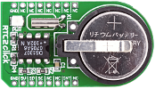
The RTC2 Click board is an accessory board in mikroBus form factor, featuring the DS1307 serial real-time clock (RTC). It is a low-power, full binary-coded decimal (BCD) clock/calendar with programmable square-wave output signal. The board uses the I2C interface for communication, and can only be used with a 5V power supply. The board features a 3V/230mA lithium battery as a backup power supply, which ensures that timekeeping operation continues even when the main power supply turns off. |
|
|
|
 |

|
|
The RTC Click board is an accessory board in mikroBus form factor. It features the PCF8583 serial real-time clock (RTC). It is a low-power, full binary-coded decimal (BCD) clock/calendar. The board uses an I2C interface for communication and features a 3V/230mA lithium battery as a backup power supply, which ensures that timekeeping operation continues even when the main power supply turns off. The board is set to use the 3.3V mikroBus power supply by default, however soldering the PWR SEL SMD jumper to the 5V position enables it to be used with 5V mikroBus systems. |
|
|
|
 |
|
|
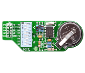
RTC board enables you to use a real-time-clock and calendar in your applications. It features an PCF8583 that keeps track of the current time even when the microcontroller is turned off. The real-time clock is driven by a special battery that is not connected to the normal power supply. The board serves as an extension of development boards which need real time data for their operation but can also be used as a part of some other devices if required. It comes with the relevant schematic and many ready-to-use examples. |
|
|
|
 |
|
|
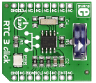
RTC3 click carries BQ32000, a real time clock with an integrated trickle charge circuit for automatic switchover to a backup power supply (the circuit maintains the backup charge with an onboard super capacitor). The clock frequency is derived from an onboard 32.768KHz oscillator. RTC3 click communicates with the target board microcontroller through mikroBUS I2C lines: SCL, SDA. In addition, the INT pin serves as a configurable interrupt output. The board is designed to use a 3.3V power supply only. |
|
|
|
 |
|
|
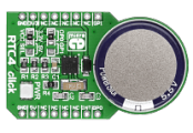
RTC4 click carries DS2417, a real time clock/calendar with a 1-Wire MicroLAN interface and a programmable interrupt for system output. The clock frequency is derived from an onboard 32.768KHz oscillator. An integrated backup energy source maintains a charge with an onboard coin cell supercapacitor. The clock has an accuracy of +/-2 minutes per month at a 25 degrees Celsius temperature. Depending on the position of the onboard jumper, RTC4 click communicates with the target board MCU either through mikroBUS AN or PWM pin (here, GPI01, GPIO0), plus the INT pin. The board is designed to use either a 3.3V or 5V power supply. |
|
|
|
 |
|
|
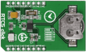
RTC5 click carries MCP79510, a real-time clock/calendar with an SPI interface (mikroBUS MISO, MOSI, SCK and CS pins); along with a programmable interrupt for system output. The clock frequency is derived from an onboard 32.768KHz oscillator. For backup power, RTC5 click has a coin-cell Lithium polymer battery connector. The chip has 64-bytes of battery-backed SRAM and 1 kbit of EEPROM for storing data, along with 128 bits of protected space for storing a unique ID. The clock/calendar automatically compensates for leap years and months shorter than 31 days. The board is designed to use a 3.3V power supply only. |
|
|
|
 |
|
|
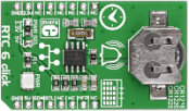
RTC6 click carries Microchip's MCP79410 Real-Time Clock/Calendar IC with built-in 64 bytes of battery-backed SRAM an additional 1 Kbit of EEPROM. 64 bits of protected EEPROM requires an unlock sequence to be unlocked, which makes it suitable for storing a unique ID or other critical information. RTC6 click tracks hours, minutes, seconds, days, months, years and weekdays, with leap year compensation until the year 2399. The clock frequency is derived from an onboard 32.768KHz crystal oscillator. Backup power is supplied by a coin-cell Lithium battery. RTC6 communicates with the target board MCU through the mikroBUS I2C interface (SCL, SDA) along with a multifunction pin (MFP, in place of default mikroBUS INT pin). The multifunctional pin (MFP) can be configured as an alarm, a square wave frequency output, or a general purpose output. The board is designed to use either a 3.3V or a 5V power supply. |
|
|
|
 |
|

