|
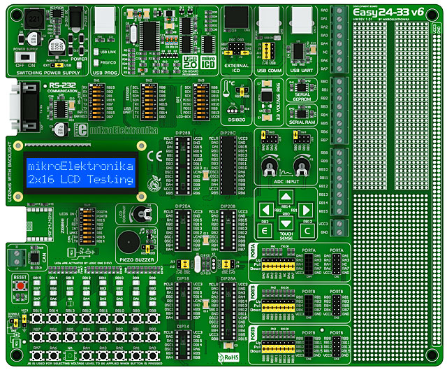
On-board USB programmer (no need to purchase an external programmer) with mikroICD for in-circuit-debugging from any of MikroElektronika's compilers. Free 2K limited demo compiler included. |
|
MikroElektronika-standard IDC10 connectors, used to easily add functionality by connecting any of a huge range of accessory boards (see "Related Items"). |
|
Example programs. |
|
USB or external AC/DC power supply option. |
|
LEDs and buttons connected to all available port pins (buttons can apply logic high or low when pressed). |
|
Pull-up / pull-down option on all port pins. |
|
Contrast adjustment on LCD display via potentiometer. |
|
ICD (in-circuit debugging) connector for use with Microchip ICD products. |
|
Reset button. |
|
Supports PIC24 and dsPIC33 microcontrollers in 14-, 18-, 20- and 28-pin DIP packages. |
|
Comes with a PIC24F16KA102 microcontroller. |
|
Has place for a 2x16 LCD display (sold separately). |
|
DS1820 temperature-sensor connector (DS1820 sold separately). |
|
Two potentiometers for ADC (analogue-to-digital converter) input. |
|
RS-232 (with MAX232), USB and USB with serial UART connectors. On-board MCP2551 CAN module with screw-terminal connector. |
|
Serial 24AA01 EEPROM with 1kbit of memory and I2C interface and serial 23K640 RAM module with SPI interface. |
|
Piezo buzzer. |
|
Prototyping area. |
|
Place for a 2.4 GHz IEEE 802.15.4 ZigBee Transceiver Module (sold separately). |
|
Capacitive-touch pads. |