RS485 2 click carries the MAX3471 half-duplex transceiver intended for lithium battery-powered RS-485/RS-422 applications. The click is designed to run on either 3.3V or 5V power supply. It communicates with the target microcontroller over UART interface with additional functionality provided by the following pins on the mikroBUS™ line: PWM, CS.
MAX3471 transceiver features
The MAX3471 draws only 1.6µA (typical) supply current from a 3.6V supply with the receiver enabled and the driver disabled. Its wide 2.5V to 5.5V supply voltage guarantees operation over the lifetime of a lithium battery.
This device contains one driver and one receiver. Its true fail-safe receiver input guarantees a logic-high receiver output when the receiver inputs are open or shorted, or when they are connected to a terminated transmission line with all drivers disabled.
The MAX3471 receiver operates at up to 64kbps and incorporates input filtering in addition to input hysteresis. This filtering enhances noise immunity when differential signals have very slow rise and fall times.
How the click works
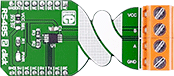
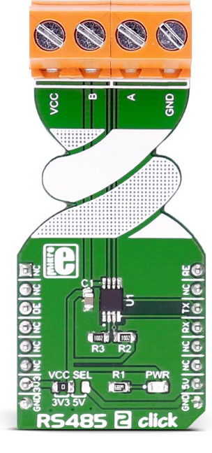
There are two pairs of screw terminals on board the RS485 2 click. The ones marked with A and B are differential high and differential low communication lines. We added two more terminals for VCC and GND reference if needed for further interfacing.
Specifications
| Type |
RS485 |
| Applications |
Battery-Powered Differential Communications |
| On-board modules |
MAX3471 half-duplex transceiver |
| Key Features |
1.6µA Supply Current with Receiver Enabled; intended for lithium battery-powered RS-485/RS-422 applications. |
| Interface |
UART |
| Power Supply |
3.3V or 5V |
| Click board size |
L (57.15 x 25.4 mm) |
Pinout diagram
This table shows how the pinout on RS485 2 click corresponds to the pinout on the mikroBUS™ socket (the latter shown in the two middle columns).
| Notes | Pin |  | Pin | Notes |
|---|
|
NC |
1 |
AN |
PWM |
16 |
RE |
Receiver output enable, active low |
|
NC |
2 |
RST |
INT |
15 |
NC |
|
| Driver output enable, active high |
DE |
3 |
CS |
TX |
14 |
RX |
UART data receive |
|
NC |
4 |
SCK |
RX |
13 |
TX |
UART data transmit |
|
NC |
5 |
MISO |
SCL |
12 |
NC |
|
|
NC |
6 |
MOSI |
SDA |
11 |
NC |
|
| Power supply |
+3.3V |
7 |
3.3V |
5V |
10 |
+5V |
Power supply |
| Ground |
GND |
8 |
GND |
GND |
9 |
GND |
Ground |
Jumpers and settings
| Designator | Name | Default Position | Default Option | Description |
|---|
| JP1 |
VCC SEL |
Left |
3V3 |
Power Supply Voltage Selection 3V3/5V, left position 3V3, right position 5V |
Programming
Code examples for RS485 2 click, written for MikroElektronika hardware and compilers are available on Libstock.
Code snippet
The following code snippet shows a part of the RS485 2 click example. One device is set as the slave, and the other is the master. Upon button press on the master, an LED light on the slave device will change its state.
01 void main()
02 {
03     systemInit();
04
05    while( 1 )
06     {
07 #ifdef MASTER_NODE
08         if (isButtonPressed())
09         {
10             ledToggle();
11             RS485_2_transmit(&cmd, 1);
12         }
13         Delay_ms(25);
14 #endif
15     }
16 }
17
18 #ifdef SLAVE_NODE
19 void RX_ISR() iv IVT_INT_USART3 ics ICS_AUTO
20 {
21     if( RXNE_USART3_SR_bit )
22     {
23         char rxByte = USART3_DR;
24
25        if (rxByte == ON_CMD)
26         {
27             LED_PIN = LED_ON;
28         }
29         else if (rxByte == OFF_CMD)
30         {
31             LED_PIN = LED_OFF;
32         }
33     }
34 }