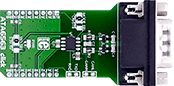
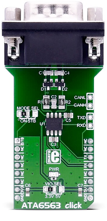
ATA6563 click carries the ATA6563 high-speed CAN transceiver. The click is designed to run on a 5V power supply. Use the VIO SEL jumper for selecting the 3.3V or 5V logic level. It communicates with the target microcontroller over UART interface, with additional functionality provided by the AN pin on the mikroBUS™ line.
ATA6563 features
The ATA6563 is a high-speed CAN transceiver that provides an interface between a controller area network (CAN) protocol controller and the physical two-wire CAN bus.
The transceiver is designed for high-speed (up to 5 Mbps) CAN applications in the automotive industry, providing differential transmit and receive capability to (a microcontroller with) a CAN protocol controller. It offers improved electromagnetic compatibility (EMC) and electrostatic discharge (ESD) performance.
The transceiver is CAN FD (Flexible data-rate) ready, meaning it has increased data rates in comparison with classic CAN.
How the click works
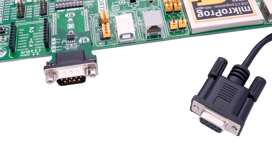
ATA6563 click is connected to a CAN bus via the DB9 cable, which then communicates with the network.
Specifications
| Type |
CAN |
| Applications |
Classical CAN and CAN FD networks in Automotive, Industrial, Aerospace, Medical and Consumer applications. |
| On-board modules |
ATA6563 high-speed CAN transceiver from Microchip |
| Key Features |
Optimized for CAN FD at 2 and 5 Mbps operation, maximum propagation delay: 210ns; the chip supports CAN 2.0 and CAN with flexible data rates. |
| Interface |
UART |
| Power Supply |
3.3V or 5V |
| Click board size |
L (57.15 x 25.4 mm) |
Pinout diagram
This table shows how the pinout on ATA6563 click corresponds to the pinout on the mikroBUS™ socket (the latter shown in the two middle columns).
| Notes | Pin |  | Pin | Notes |
|---|
| Standby select |
STBY |
1 |
AN |
PWM |
16 |
NC |
|
|
NC |
2 |
RST |
INT |
15 |
NC |
|
|
NC |
3 |
CS |
TX |
14 |
RX |
UART data receive |
|
NC |
4 |
SCK |
RX |
13 |
TX |
UART data transmit |
|
NC |
5 |
MISO |
SCL |
12 |
NC |
|
|
NC |
6 |
MOSI |
SDA |
11 |
NC |
|
| Power supply |
+3.3V |
7 |
3.3V |
5V |
10 |
+5V |
Power supply |
| Ground |
GND |
8 |
GND |
GND |
9 |
GND |
Ground |
Jumpers and settings
| Designator | Name | Default Position | Default Option | Description |
|---|
| JP1 |
VIO SEL |
Left |
3V3 |
VIO Supply Voltage Selection 3V3/5V, left position 3V3, right position 5V |
| JP2 |
MODE SEL |
Left |
ON |
Selection of the standby feature; default is always on, right option switches to the STB pin on the mikroBUS™ |
Additional pins
| Name | I/O | Description |
|---|
| CANL |
I/O |
CAN lines, same as on DB9 connector |
| CANH |
I/O |
CAN lines, same as on DB9 connector |
| TXD |
I |
UART lines, same as on the mikroBUS™ |
| RXD |
O |
UART lines, same as on the mikroBUS™ |
Programming
Code examples for ATA6563 click, written for MikroElektronika hardware and compilers are available on Libstock.
Code snippet
A simple example of the ATA6563 library usage. The example waits until 8 bytes are received on the RX and then prints the received data using the other UART module.
01 void main()
02 {
03     int i = 0;
04     system_init();
05     while( 1 ) {
06         if( Button( &GPIOA_IDR , 5, 100, 1 ) ){
07             ata6563_send( TX_DATA, sizeof( TX_DATA ) );
08             TFT_Write_Text( "Data Sent", 50, 100 );
09         }
10         if( ( chk = ata6563_rdy() ) == 8 ){
11             ata6563_read( buf, chk );
12             for( i = 0; i < chk; i++ )
13                  UART1_Write( buf[ i ] );
14         }
15     }
16 }