 |

|
|
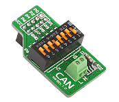
The CAN-1 Board is an accessory board designed to be used with microcontrollers that have CAN support. It has the MCP2551 CAN transceiver. Use the IDC10 to connect the CAN-1 board to a MCU, thus enabling it to access the CAN network. |
|
|
|
 |

|
|
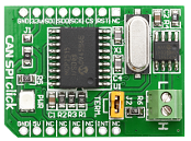
The CAN SPI click board is an accessory board in the mikroBus form factor. It is the best solution to add CAN connectivity to your microcontroller with SPI interface. The board features either the SN65HVD230 (3.3V) or MCP2551 (5V) CAN transciever circuit which provides a CAN serial communication physical layer, in accordance with the ISO 11898 standard. It is designed for operation in especially-harsh environments; and features cross-wire protection, loss-of-ground and over-voltage protection, over-temperature protection, as well as wide common-mode range. |
|
|
|
 |

|
|
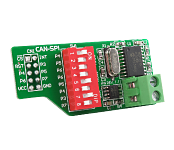
The CANSPI Board is an accessory board that includes the MCP2515 CAN controller and MCP2551 transceiver. It is capable of transmitting and receiving both standard and extended data and remote frames. The CAN controller also has two acceptance masks and six acceptance filters that are used to filter out unwanted messages, thus reducing the host MCUs overhead. It can be used with all devices that have SPI support. The board is designed to run on 5V only. |
|
|
|
 |

|
|
CAN Isolator click provides isolated CAN communication. It carries the ADM3053 signal and power isolated CAN transceiver with an integrated isolated DC-to-DC converter. The click is designed to run on either 3.3V or 5V power supply. CAN Isolator click communicates with the target microcontroller over UART interface. |
|
|
|
 |

|
|
MCP25625 click is a mikroBUS add-on board carrying a Microchip CAN controller with an integrated transceiver. It meets the automotive requirement for high speed operation (up to 1 Mb/s).
Named after the main chip, MCP25625 click also has a RS232 port, which is a standard connector for CAN communications. Additionally, the two CAN wires (CANL and CANH) can also be connected directly through two pins on the right edge of the board.
The click communicates with the target MCU through the SPI interface - although there are additional options that take the load off the target board MCU. To that end, all 16 mikroBUS pins are connected. There's a clock output, a Request To Send, an Interrupt, standby, reset and more. MCP25625 click can work with both 3.3V or 5V logic levels. |
|
|
|
 |

|
|
MCP2542 click is a mikroBUS add-on board with a Microchip CAN FD Transceiver with Wake-Up Pattern. The physical layer is compliant with CAN 2.0 and CAN with Flexible Data Rate (CAN FD). It is designed specifically for high-speed CAN FD applications with communication speeds of up to 8 Mbps. Longer than usual BUS lengths are supported thanks to the improved maximum propagation delay.
The board has a standard RS232 port for CAN communications.
MCP2542 click communicates with the target board MCU through mikroBUS UART interface with an additional StandBy pin (STBY, in place of default mikroBUS AN pin). Two additional pairs of pins on the right edge of the board offer separate UART connection as well as a CAN interface.
The board is designed to use either a 3.3V or 5V power supply. |
|
|
|
 |

|
|
MCP2517FD click serves as a CAN connector. It carries a DB9 9-pin connector, as well as ATA6563 high-speed CAN transceiver. The click is designed to run on either 3.3V or 5V power supply. It communicates with the target microcontroller through SPI interface, with additional functionality provided by the following pins on the mikroBUS™ socket: AN, PWM, INT, CS, SCK, MISO, MOSI, TX and RX. |
|
|
|
 |

