USB UART 3 click is a versatile and feature-rich USB to UART interface from Silicon Labs. It uses CP2102N which is a part of their USBXpress™ family. These devices are designed to quickly add a USB 2.0 full-speed compliant UART interface for custom applications, by eliminating firmware complexity and reducing development time. The Click board™ requires appropriate drivers to be installed in the host OS, in order to support the virtual COM port functionality. Once installed, this device offers amazing connectivity options, up to 3 Mbaud, a very low number of external components, simplified setup of the advanced options via the GUI-based configurator (if required), out-of-the-box functionality with the royalty-free virtual COM port drivers, provided by the Silicon Labs.
Besides the highly integrated USB to UART interface IC, this Click board™ is equipped with the additional ESD protection for the USB port, as well as the required signalization LEDs (RX, TX, power LED, and USB suspend LED). Full UART interface implementation with the high-speed virtual COM port, along with the USB Wake Up and Suspend pins, make this Click board™ a perfect choice for adding a reliable USB to UART interface to any custom application, greatly simplifying the design and cutting the time to market.
How does it work?
The main component of the USB UART 3 click is the CP2102N, a highly integrated USB to UART interface, from Silicon Labs. This IC adds USB to UART communication for embedded applications, registering itself as the virtual COM port, once the required drivers are installed. The device itself features the entire stack needed for the communication, so no firmware is required to handle the data transfer process between the UART and the USB. It offers a range of data rates from 300bps up to 3Mbps, hardware flow control support, 512 bytes long FIFO buffer, USB suspend and wakeup, 960 bytes of non-volatile configuration memory (EEPROM), and more.
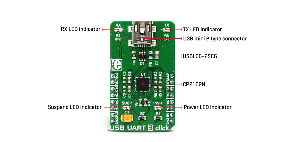
The device comes with the pre-programmed factory settings, so it works as the virtual COM port device, requiring the appropriate Virtual COM port device drivers. In this scenario, it will offer a fully RS232 compliant virtual COM port, which can be used and configured as any other COM port on the computer, with the USB data available at the UART RX and TX pins. The USB port of the Click board™ is ESD protected by the USBLC6-2SC6, a very low capacitance ESD protection IC, and it is compliant with the USB 2.0 standard.
When using the USBXpress™ drivers, the device can be configured by using the Xpress Configurator in the Simplicity Studio, a software application, developed by Silicon Labs. This provides a graphical user interface for simplified configuration of the various parameters of this device.
By configuring the communication to use the hardware handshaking, it is possible to utilize the internal FIFO buffer for improved speed and reliability. This will require using the RTS and CTS pins. Hardware flow control uses these pins to signal nearly full status of the internal FIFO buffer. RTS pin will report that the FIFO buffer is almost full by being pulled to a HIGH logic level. On the other side, the CTS pin detects this condition, and when pulled to a HIGH logic level, the data will not be sent anymore (up to two bytes will be sent after the CTS pin is driven to a HIGH logic state). By using the hardware flow control, no receiver overrun conditions will occur at high baud rates. Therefore, it is advised to use it for high baud rate communication - 1 Mbaud or more. Software handshaking is also supported, by using the XON and XOFF characters. RTS and CTS pins are routed to the mikroBUS™ INT and CS pins, respectively.
USB suspend event will be indicated on two CP2102N pins: SUSPEND and SUSPEND#. These pins will be pulled to a LOW and HIGH level respectively when the USB port suspends the IC. The SUSPEND# line is used to light up a LED indicator labeled as SUSP, while the SUSPEND pin is routed to the AN pin of the mikroBUS™, indicating the USB suspend event to the MCU. This can be used for power saving purposes, as the external circuitry can be turned off in the case of USB suspend event.
The device also features a Remote Wake function. When the USB port is in suspend mode, by pulling the WAKEUP pin to a LOW logic level, the CP2102N will begin the USB wake-up sequence. Please note that the operating system has to allow this, by setting the appropriate power management options (in Windows OS navigate to Properties > Power Management > Allow this device to wake up the computer). The WAKEUP pin is routed to the PWM pin of the mikroBUS™. The WAKEUP pin is multiplexed with the GPIO3 pin function and it can be reconfigured if the WAKEUP function is not required.
A hardware reset pin is also available. This pin is routed to the mikroBUS™ RST pin, and driving it to a LOW logic level will reinitialize the device. Note that the SUSP LED will be lit after POR or any other type of reset, during the USB Enumeration sequence.
UART RX and TX pins are routed to the appropriate mikroBUS™ UART pins and are used to send (receive) UART type of communication from (to) the host MCU. The UART data is exchanged by these pins with the internal FIFO buffer. This allows the USB transceiver to send (receive) data packets to (from) the computer and exchange them with the UART section. The data traffic is indicated by two onboard LED indicators labeled as TX and RX. These LEDs are multiplexed with the GPIO0 and GPIO1 pin functions, so changing them in the configurator is not advised.
Silicon Labs offer an extensive documentation, explaining operation and functionality of their software application, so it can be referenced if more information is required. The link to the virtual COM port drivers is provided below, in the downloads section. The drivers will be installed according to the configurable PID and VID values of the CP2102N device. By default, the device is set to work as the virtual COM port (VCP) USB to UART bridge. For building customized drivers, please consult the Silicon Labs documentation.
Specifications
| Type |
USB |
| Applications |
It can be used whenever a simple and ready-made solution for interfacing USB to UART is needed, including both software and hardware flow control. |
| On-board modules |
CP2102N, a member of USBXpress™ family, highly integrated USB to UART interface, from Silicon Labs. |
| Key Features |
Requires no dedicated firmware for handling the USB to UART communication, software, and hardware flow control, high-speed communication up to 3Mbaud, etc. |
| Interface |
UART,USB |
| Input Voltage |
3.3V,5V |
| Click board size |
M (42.9 x 25.4 mm) |
Pinout diagram
This table shows how the pinout on USB UART 3 click corresponds to the pinout on the mikroBUS™ socket (the latter shown in the two middle columns).
| Notes | Pin |  | Pin | Notes |
|---|
| USB suspend |
SUS |
1 |
AN |
PWM |
16 |
WUP |
Wake up |
| Reset |
RST |
2 |
RST |
INT |
15 |
RTS |
Ready to Send |
| Clear to Send |
CTS |
3 |
CS |
RX |
14 |
TX |
UART TX (transmit) |
|
NC |
4 |
SCK |
TX |
13 |
RX |
UART RX (receive) |
|
NC |
5 |
MISO |
SCL |
12 |
NC |
|
|
NC |
6 |
MOSI |
SDA |
11 |
NC |
|
| Power supply |
3.3V |
7 |
3.3V |
5V |
10 |
5V |
Power supply |
| Ground |
GND |
8 |
GND |
GND |
9 |
GND |
Ground |
Onboard settings and indicators
| Label | Name | Default | Description |
|---|
| LD1 |
PWR |
- |
Power LED indicator |
| LD2 |
SUSP |
- |
USB Suspend LED indicator |
| LD3 |
TX |
- |
Data Send (TX) LED indicator |
| LD4 |
RX |
|
Data Receive (RX) LED indicator |
Software support
We provide a demo application for USB UART 3 click on our Libstock page, as well as a demo application (example), developed using MikroElektronika compilers. The demo can run on all the main MikroElektronika development boards.
Library Description
Library performs IR and temperature measurement. The sensor gets an IR picture of the detected object (body) and measures ambient temperature, compares that two measurements and shows the IR picture as a 16x4 matrix. For more details check the documentation.
Key functions:
void usbuart3_writeByte(uint8_t input) - Write Single Byte.uint8_t usbuart3_readByte() - Read Single Byte.uint8_t usbuart3_byteReady() - Check for the new byte received.
Example description
The application is composed of three sections:
- System Initialization - Initializes UART module.
- Application Initialization - Driver intialization.
- Application Task - (code snippet) - Checks if new data byte has received in the RX buffer (ready for reading), and if ready than reads one byte from the RX buffer. In the second case, the application task writes the message data via UART.
void applicationTask()
{
 char tmp;
 uint8_t rdyFlag;

// RECEIVER - UART polling

 rdyFlag = usbuart3_byteReady();

 if (1 == rdyFlag)
 {
 tmp = usbuart3_readByte();
 mikrobus_logWrite( &tmp, _LOG_BYTE );
 }

// TRANSMITER - TX each 2 sec

  for (tmp = 0; tmp < 9; tmp++)
 {
 usbuart3_writeByte( MESSAGE_DATA[tmp] );
 mikrobus_logWrite( "MESSAGE SENT", _LOG_LINE );
 }
 Delay_ms(2000);

}
The full application code, and ready to use projects can be found on our Libstock page.
Other MikroElektronika libraries used in the example:
Additional notes and information
Depending on the development board you are using, you may need USB UART click, USB UART 2 click or RS232 click to connect to your PC, for development systems with no UART to USB interface available on the board. The terminal available in all MikroElektronika compilers, or any other terminal application of your choice, can be used to read the message.