OBDII click offers a unique opportunity to tap into the car diagnostic systems. It features the STN1110 Multiprotocol OBD to UART Interface, developed by the ScanTool technologies. This click can be used for the communication with the Electronic Control Unit (ECU) of a vehicle, via several different OBD II diagnostic protocols such as CAN, K LINE, L LINE and J1850. The STN1110 IC is used to process requests sent by the MCU via the UART interface and return back the responses from the ECU network nodes
OBDII click offers a unique opportunity to tap inside the car diagnostic systems. It features the STN1110 Multiprotocol OBD to UART Interface, developed by the ScanTool technologies. This click can be used for the communication with the Electronic Control Unit (ECU) of a vehicle, via several different OBD II diagnostic protocols such as CAN, K LINE, L LINE and J1850. The STN1110 IC is used to process requests sent by the MCU via the UART interface and return back the responses from the ECU network nodes.
The STN1110 Multiprotocol OBD to UART IC is built around a fast 16bit processor core and has large memory buffer. It also features automatic protocol recognition, it is fully compatible with the ELM327 and ELM327 Extended AT command set and can be used on UART speed up to 10Mbps. Those features make this click more than a perfect solution for various designs, including custom car dashboards, OBD data loggers, Automotive diagnostic scan tools and similar applications.
How does the click work?
OBD or On-board Diagnostic is a set of standards for implementing a computer-based system to control and diagnose vehicles. OBD II is the second generation of this standard, which was first introduced in the ‘80s. Over time, several revisions of this standard were made and from just a few simple light indicators, the OBD grew into a fully-fledged digital diagnostic standard, with strictly defined communication rules and the type of connectors.
The standard prescribes a set of defined PIDs or Parameter IDs to communicate with the vehicle onboard computer (ECU) and return values from the corresponding locations of the vehicle's controller network, related to a specific PID. There are 10 modes of operation described in the latest OBD II standard. Vehicle manufacturers are not required to support all 10 modes and may add some additional modes. The expected response for each PID is strictly defined, along with information on how to translate the response into meaningful data.
STN1110 is an OBD to UART interpreter IC that can be used to convert messages between the currently supported OBD-II protocols and the UART. It is fully compatible with the commonly used ELM327 device command set. OBD II standard also prescribes that each OBD II compliant vehicle should be equipped with a standard diagnostic connector (DLC), which makes connecting and reading data from various types of vehicles possible by using the same device.
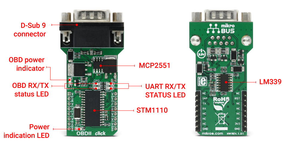
To achieve successful communication with various systems used inside the vehicle diagnostic network, the STN1110 needs the signals to be converted on a physical level. For this reason, the Click Board also comes equipped with the MCP2551 - an ISO-11898 standard compliant CAN signal transceiver, as well as the LM339 - quad differential comparator IC, that is used to convert K Line, L Line and J1850 line signals into a proper digital format. There is a separate analog pin available on the STN1110 IC, which is used for the car battery voltage measurement. This function is handy when checking communication on the UART side of the IC. Besides requesting the voltage level information from the ECU via the command, it can also be measured directly from the battery voltage divider, with no special communication protocol used.
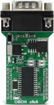
The click is equipped with four signaling LEDs, that are used to monitor data transfer on the click-OBD side, as well as on the click-MCU side (OBD RX/TX and UART RX/TX). Besides the Power LED (PWR) used to indicate that the click, there is also a LED that indicates the presence of battery voltage on the OBD connector, and it is labeled as BAT. The OBDII click comes equipped with the D-Sub 9 connector (also known as DB9) that allows using a standard OBDII cable.
Note: The OBDII cable does not come with the package.
After the initial protocol auto-recognition (which might require the ignition switch to be turned on and the initialization AT command to be sent), all the communication between the vehicle ECU and the STN1110 is done automatically, so it is possible to get readings of the vehicle systems status effortlessly, by sending simple AT commands via the UART pins of the click. MikroElektronika provides simplified libraries that take care of the proper communication between the click and the MCU via the UART. For the complete list of available AT commands, please refer to the product documentation.
Specifications
Type
CAN
Applications
It can be used for diagnostic purposes, or for making a custom car dashboard. The click intermediates between the MCU and the vehicle Electronic Control Unit (ECU).
On-board modules
STN1110 from ScanTool, an OBD to UART interpreter IC designed to provide bi-directional half-duplex communication with the vehicle's On-Board Diagnostic System (OBD-II).
Key Features
Full OBD-II support, compatible with the ELM327 AT extended command set, fast communication speed and reliability, superior automatic protocol detection algorithm, large memory buffer, separate voltage input for the direct battery monitoring.
Interface
UART
Input Voltage
3.3V
Click board size
L (57.15 x 25.4 mm)
Pinout diagram
This table shows how the pinout on OBDII click corresponds to the pinout on the mikroBUS™ socket (the latter shown in the two middle columns).
Notes
Pin
Pin
Notes
NC
1
AN
PWM
16
NC
Reset
RST
2
RST
INT
15
INT
Interrupt
NC
3
CS
RX
14
TX
UART TX
NC
4
SCK
TX
13
RX
UART RX
NC
5
MISO
SCL
12
NC
NC
6
MOSI
SDA
11
NC
Power supply
3V3
7
3.3V
5V
10
NC
Ground
GND
8
GND
GND
9
GND
Ground
Onboard settings and indicators
Label
Name
Default
Description
PWR
Power LED
-
Power indication LED
BTR
Battery OK
-
OBD battery voltage indicator LED
RX OBD
RX OBD LED
-
Indicates RX activity on the OBD communication
TX OBD
TX OBD LED
-
Indicates TX activity on the OBD communication
RX UART
RX UART LED
-
Indicates RX activity on the UART communication
TX UART
TX UART LED
-
Indicates TX activity on the UART communication
Software support
We provide a library for OBDII click on our LibStock page, as well as a demo application (example), developed using MikroElektronika compilers and mikroSDK. The demo can run on all the main MikroElektronika development boards.
Library description
The library carries generic functions, necessary for communication with the module.
Key functions:
obdII_sendCommand- Sends provided command to the module
obdII_readResponse - Reads current response inside buffer
obdII_process- State machine function. This function is being called frequently
Examples Description
The example demonstrates how to read RPM from your vehicle.
System Initialization - Initializes UART module and GPIO pins
Application Initialization - Powers on the module and sets it to Automatic protocol detection by sending "ATSP0"
Application Task - (code snippet) - Sequentially sends command for RPM and converts read response to a valid RPM value
Note that not all vehicles use the same set of commands - it might happen that routine for reading RPM on your vehicle is not the same as the ones provided in the example.
The full application code and ready to use projects can be found on our LibStock page.
Other MikroElektronika libraries used in the example:
Conversions
String
Stdlib
Additional notes and information
Depending on the development board you are using, you may need USB UART click, USB UART 2 click or RS232 click to connect to your PC, for development systems with no UART to USB interface available on the board. The terminal available in all MikroElektronika compilers, or any other terminal application of your choice, can be used to read the message.
mikroSDK
This click board is supported with mikroSDK, the MikroElektronika Software Development Kit. To download mikroSDK visit LibStock. For more information about SDK, visit the official page.