How does it work?
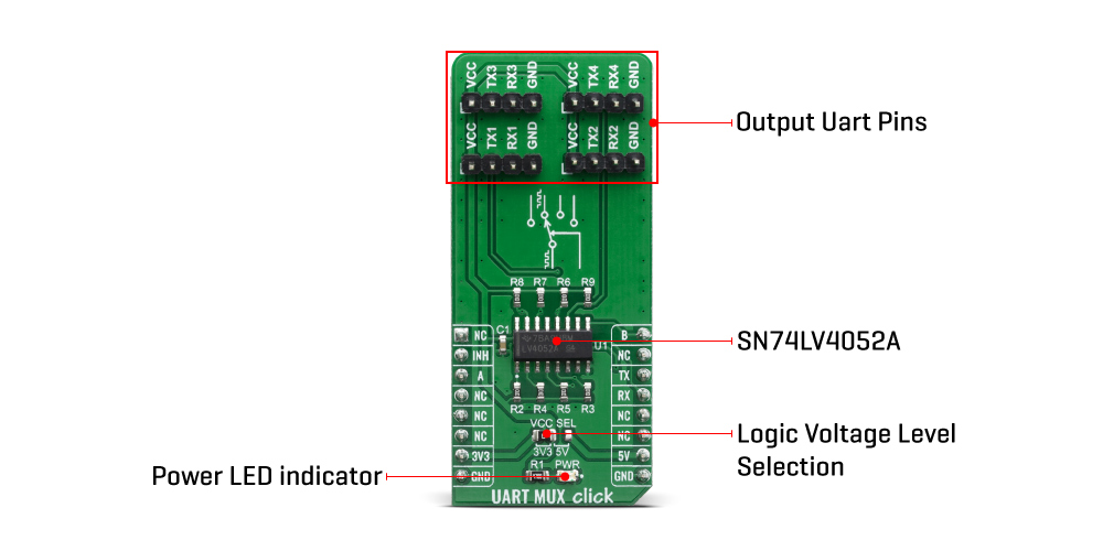
UART Mux click is equipped with the SN74LV4052A, a Dual 4-Channel Multiplexer and Demultiplexer, from Texas Instruments. Two control pins are used to switch to one of four available outputs, from a single UART input, from the mikroBUS™. Control pins labeled as A and B, are routed to the mikroBUS™ and can be operated by both 3.3V and 5V MCUs. The fourth control pin is labeled as EN pin, and it is used to enable the internal multiplexing switches of the IC, when is set to a HIGH logic level (it is active HIGH). A and B pins are routed to CS and PWM pins of the mikroBUS™ respectively. The active low Inhibit (INH) tri-state all the channels when high and when low, depending on the A and B inputs, one of the four independent input/outputs is connected to the UART communication pins. INH pin is routed to the RST pin on the mikroBUS™.
The ultra-low leakage current ensures that there is no signal interference from the inputs that are not selected by the A and B pins. A low crosstalk also ensures that the signal on one channel remains clean of interferences caused by other channels. This ensures a reliable operation of the IC and the Click board™ itself.
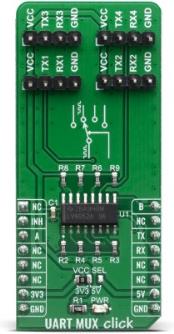
The output signals can be connected via the 2x4 pin headers. Besides RX and TX pins, every output also has dedicated VCC and GND pins avalilable, so that user can easily route multple devices with this Click board™. Independent power supply input allows the user to work with a wide range of signal amplitudes, depending on the application requirements, as long as the power supply stays within the limits.
More information about the SN74LV4052A can be found in the attached datasheet. However, the Click board™ comes equipped with a library that contains easy to use functions and a usage example that may be used as a reference for the development.
UART Mux click offers a selection between 3.3V and 5V operation, with the onboard SMD jumper, labeled as PWR SEL. This allows both 3.3V and 5V MCUs to be interfaced with this Click board™.
Specifications
| Type |
DAC |
| Applications |
Telecomunications, Infotainment, Signal Gating and Isolation, Home Appliances, Programmable Logic Circuits, Modulation and Demodulation |
| On-board modules |
SN74LV4052A, a Dual 4-Channel Analog Multiplexer and Demultiplexer from Texas Instruments |
| Key Features |
High On-Off Output-Voltage Ratio, Extremely Low Input Current, 2-V to 5.5-V VCC Operation |
| Interface |
GPIO,UART |
| Compatibility |
mikroBUS |
| Click board size |
L (57.15 x 25.4 mm) |
| Input Voltage |
3.3V or 5V |
Pinout diagram
This table shows how the pinout on UART Mux Click corresponds to the pinout on the mikroBUS™ socket (the latter shown in the two middle columns).
| Notes |
Pin |
 |
Pin |
Notes |
|---|
| |
NC |
1 |
AN |
PWM |
16 |
B |
Control Pin B |
| Inhibit Input |
INH |
2 |
RST |
INT |
15 |
NC |
|
| Control Pin A |
A |
3 |
CS |
RX |
14 |
TX |
UART Transmit |
| |
NC |
4 |
SCK |
TX |
13 |
RX |
UART Receive |
| |
NC |
5 |
MISO |
SCL |
12 |
NC |
|
| |
NC |
6 |
MOSI |
SDA |
11 |
NC |
|
| Power Supply |
3.3V |
7 |
3.3V |
5V |
10 |
5V |
Power Supply |
| Ground |
GND |
8 |
GND |
GND |
9 |
GND |
Ground |
Onboard settings and indicators
| Label |
Name |
Default |
Description |
|---|
| PWR |
PWR |
- |
Power LED Indicator |
| J1 |
VCC SEL |
Left |
Power supply voltage selection: left position 3.3V, right position 5V |
Software Support
We provide a library for the UART Mux Click on our LibStock page, as well as a demo application (example), developed using MikroElektronika compilers. The demo can run on all the main MikroElektronika development boards.
Library Description
The library covers all the necessary functions that enables the usage of the UART Mux click board. User can write, read or check if there is a new byte received on all four channels that are available. Library also offers the functions taht allow user to inhibit or uninhibit the communication.
Key functions:
void uartmux_writeByte(uint8_t input) - Writes sinle byteuint8_t uartmux_readByte() - Read received byteuint8_t uartmux_byteReady() - Checks is there a new byte received
Examples description
The application is composed of three sections :
- System Initialization - Initializes UART, GPIO and LOG structures, sets RST, CS and PWM pins as output.
- Application Initialization - Initalizes UART driver, uninhibites communication and makes an initial log.
- Application Task - (code snippet) This example demonstrates the use of UART Mux click board by eather sending or receiving the message on channel one of the device.
void applicationTask()
{
    char tmp;

// RECEIVER - UART polling
/*
    if ( 1 == uartmux_byteReadyChann1() )
    {
        tmp = uartmux_readByteChann1();
        mikrobus_logWrite( &tmp, _LOG_BYTE );
    }
*/
// TRANSMITER - TX each 2 sec

    for (tmp = 0; tmp < 9; tmp++)
    {
        uartmux_writeByteChann1( MESSAGE_DATA[tmp] );
    }

    Delay_ms(2000);

}
The full application code, and ready to use projects can be found on our LibStock page.
Other mikroE Libraries used in the example:
Additional notes and informations
Depending on the development board you are using, you may need USB UART click, USB UART 2 click or RS232 click to connect to your PC, for development systems with no UART to USB interface available on the board. The terminal available in all MikroElektronika compilers, or any other terminal application of your choice, can be used to read the message.
mikroSDK
This Click board™ is supported with mikroSDK - MikroElektronika Software Development Kit. To ensure proper operation of mikroSDK compliant Click board™ demo applications, mikroSDK should be downloaded from the LibStock and installed for the compiler you are using.
For more information about mikroSDK, visit the official page.
Resources
Downloads