|
|
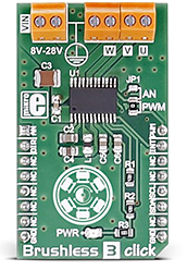
Brushless 3 click carries the DRV10983, a three-phase sensorless motor driver with integrated power MOSFETs. When an external power supply is applied, you can drive a brushless DC motor through the PWM pin, AN pin or I2C interface. It communicates with the target microcontroller over I2C interface, with the additional functionality provided by the following pins on the mikroBUS™ line: PWM, AN, INT, RST. |
|
|
|
Brushless 3 click carries the DRV10983, a three-phase sensorless motor driver with integrated power MOSFETs. When an external power supply is applied, you can drive a brushless DC motor through the PWM pin, AN pin or I2C interface. It communicates with the target microcontroller over I2C interface, with the additional functionality provided by the following pins on the mikroBUS??? line: PWM, AN, INT, RST.
A 3 wire BLDC motor can be connected over the screw terminals.
.jpg)
DRV10983 driver features
The DRV10983 is a three-phase sensorless motor driver with integrated power MOSFETs, which can provide continuous drive current up to 2A.
The DRV10983 uses a proprietary sensorless control scheme to provide continuous sinusoidal drive, which significantly reduces the pure tone acoustics that typically occurs as a result of commutation.
The interface to the device is designed to be simple and flexible. The motor can be controlled directly through PWM, analog, or I2C inputs. Motor speed feedback is available through either the FG pin or I2C.
Specifications
| Type |
DC |
| Applications |
The automotive industry, drones (because of the good power-to weight ratio of brushless motors), computers, medical equipment, HVAC systems, small home appliances, robotics, battery powered systems, small cooling fans in computers, toys, etc. |
| On-board modules |
DRV10983, a three-phase sensorless motor driver with integrated power MOSFETs. |
| Key Features |
Input voltage range from 8V to 28V |
| Interface |
GPIO,I2C |
| Click board size |
M (42.9 x 25.4 mm) |
Pinout diagram
This table shows how the pinout on Brushless 3 click corresponds to the pinout on the mikroBUS??? socket (the latter shown in the two middle columns).
| Notes | Pin |  | Pin | Notes |
|---|
|
NC |
1 |
AN |
PWM |
16 |
PWM |
PWM output |
| Direction |
DIR |
2 |
RST |
INT |
15 |
INT |
FG signal output |
|
NC |
3 |
CS |
TX |
14 |
NC |
|
|
NC |
4 |
SCK |
RX |
13 |
NC |
|
|
NC |
5 |
MISO |
SCL |
12 |
SCL |
I2C clock |
|
NC |
6 |
MOSI |
SDA |
11 |
SDA |
I2C data |
|
NC |
7 |
3.3V |
5V |
10 |
NC |
|
| Ground |
GND |
8 |
GND |
GND |
9 |
GND |
Ground |
Jumpers and settings
| Designator | Name | Default Position | Default Option | Description |
|---|
| JP1 |
SPEED |
Left |
PWM |
Speed mode selection between analog and PWM. |
Programming
Code examples for Brushless 3 click, written for MikroElektronika hardware and compilers are available on Libstock.
Code snippet
The following code snippet sets the motor paremeters and measures the motor velocity.
01 sbit BRUSHLESS_3_DIR_PIN at LATC.B0;
02 sbit BRUSHLESS_3_DIR_PIN_Direction at TRISC.B0;
03 sbit BRUSHLESS_3_PWM_PIN at LATC.B1;
04 sbit BRUSHLESS_3_PWM_PIN_Direction at TRISC.B1;
05 uint8_t motorParameters [12] = { 0x39, 0x1E, 0x3A, 0x08, 0x50, 0xDA, 0x8B, 0x10, 0x27, 0x37, 0x04, 0x0C} ;
06 uint16_t Velocity;
07 char text[10];
08 void systemInit()
09 {
10     ANCON0 = 0x00;
11     ANCON1 = 0x00;
12     ANCON2 = 0x00;
13     BRUSHLESS_3_DIR_PIN_Direction = 0;
14     BRUSHLESS_3_PWM_PIN_Direction = 0;
15     I2C1_Init (100000);
16     Delay_ms(100);
17     BRUSHLESS_3_I2CdriverInit( I2C1_Start, I2C1_Stop, I2C1_Repeated_Start, I2C1_Wr, I2C1_Rd);
18     UART1_Init(9600);
19     Delay_ms(100);
20     UART1_Write_Text("Init");
21 }
22 void Brushless_3_Init()
23 {
24     BRUSHLESS_3_DIR_PIN = 0;
25     BRUSHLESS_3_PWM_PIN = 1;
26     writeParameters(motorParameters);
27 }
28 void Brushless_3_Task()
29 {
30     getSpeed(&Velocity);
31     IntToStr(Velocity,text);
32     UART1_Write_Text( "Motor freq :" );
33     UART1_Write_Text(text);
34     UART1_Write_Text( "Hzrn" );
35     delay_ms(1000);
36 }
37 void main()
38 {
39     systemInit();
40     Brushless_3_Init();
41     while( 1 )
42     {
43             Brushless_3_Task();
44     }
45 }
|

