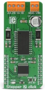
Stepper 7 click is a bipolar step motor driver. It features an H-bridge bipolar step motor driver, which supports full and half step control modes. Stepper 7 click also carries a port expander so that the communication can be done with a minimal number of pins, through the mikroBUS™ SPI bus.
Stepper 7 click offers thermal protection, integrated kickback voltage protection, it has a wide range of input voltage, protection against current shoot-through the H-Bridge and reasonably high current capability. These features make Stepper 7 click an ideal solution for driving motors in any application that demands a precise and safe step motor driver.
Stepper 7 click is a bipolar step motor driver. It features an H-bridge bipolar step motor driver, which supports full and half step control modes. Stepper 7 click also carries a port expander so that the communication can be done with a minimal number of pins, through the mikroBUS™ SPI bus.
Stepper 7 click offers thermal protection, integrated kickback voltage protection, it has a wide range of input voltage, protection against current shoot-hrough the H-Bridge and reasonably high current capability. These features make Stepper 7 click an ideal solution for driving motors in any application that demands a precise and safe step motor driver.
How does it work?
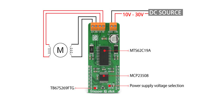
This click board™ is equipped with two integrated circuits. The step motor driver IC is the MTS62C19A, a dual full-bridge motor driver from Microchip. This IC internal structure is somewhat symmetrical. It features two MOSFET H-bridges used to drive two coils of a bipolar step motor in both directions. The MTS62C19A uses a wide input voltage range - from 10V to 30V. This is the voltage used to energize the motor coils. A separate voltage level is used for the logic sections of this IC and it is obtained from the mikroBUS™ +5V rail. The MTS62C19A has two PHASE inputs which are used to control the direction of current flow through H-bridges and thus, the motor coils.
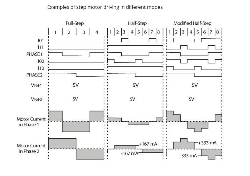
The output current level is controlled by an internal PWM circuit, which is configured using two logic inputs (Ix0 and Ix1), a current sense resistor, and the voltage on the VREFx input - set to +5V on the Stepper 7 click. By setting states on the Ix0 and Ix1 pins, the output current through the motor windings can be limited to 0%, 33%, 67% and 100% of the maximum output current, which is set to about 500mA. This setup allows controlling step motor in both full step and half step modes, by toggling states on the six control pins: PHASE1, PHASE2, I01, I02, I11, and I12.
The bipolar step motor coils can be connected to the onboard screw terminals. There are two terminals, used to connect each of the step motor coils. The third connector is used to connect an external voltage, ranging from 10V to 30V, depending on the used motor voltage requirements. It should be noted that without a valid external voltage connected to this terminal, the motor will not work. Also, it should be noted that 40V is an absolute maximum voltage allowed as per datasheet, thus the overtemperature protection might be activated when driving heavier loads. The recommended maximum voltage should not exceed 30V, as stated on the silk layer of the PCB.
All of the MTS62C19A control lines are routed to the second IC on Stepper 7 board, which is the MCP23S08, a well-known 8bit I/O expander with a serial interface, used on many of the MikroElektronika's designs for its simplicity and reliability. It allows the control lines of the MTS62C19A IC to be driven via the SPI and few pins it uses - reducing the required pin count of the Stepper 7 click. This also allows for sending compact SPI messages, instead of toggling several pins at once - which can introduce problems with timing sometimes, especially when those pins belong to different MCU ports. Changing the supply voltage for the port expander allows for different SPI logic levels to be used for the communication - 3.3V or 5V, depending on host MCU. This can be accomplished by switching the position of the onboard SMD jumper, labeled as PWR SEL.
By changing states of the six control pins, it is possible to drive the step motor in full step mode as well as the half step mode. The tables below this text can also be found in the MTS62C19A datasheet, and provide detailed information about how to set the pin states. However, provided MikroElektronika libraries contain simple and intuitive functions to fully control the bipolar step motor, connected to Stepper 7 click. Their usage is demonstrated in the included example application, which can be used as a reference for a custom design.
Specifications
Type
Stepper
Applications
An ideal solution for driving motors in any application that demands a precise and safe step motor driver.
On-board modules
MTS62C19A Dual Full-Bridge Motor Driver, MCP23S08 8bit I/O Expander with Serial Interface, both from Microchip
Key Features
Thermal protection, integrated kickback voltage protection, it has a wide range of input voltage, protection against current shoot-through the H-Bridge and reasonably high current capability
Interface
GPIO,SPI
Input Voltage
3.3V or 5V
Click board size
L (57.15 x 25.4 mm)
Pinout diagram
This table shows how the pinout on Stepper 7 click corresponds to the pinout on the mikroBUS™ socket (the latter shown in the two middle columns).
Notes
Pin
Pin
Notes
NC
1
AN
PWM
16
NC
Reset
RST
2
RST
INT
15
NC
Chip Select
CS
3
CS
RX
14
NC
SPI Clock
SCK
4
SCK
TX
13
NC
SPI Data In
SDO
5
MISO
SCL
12
NC
SPI Data Out
SDI
6
MOSI
SDA
11
NC
Power Supply
3V3
7
3.3V
5V
10
5V
Power Supply
Ground
GND
8
GND
GND
9
GND
Ground
Stepper 7 click electrical specifications
Description
Min
Typ
Max
Unit
Input Voltage (TB1)
10
30
V
Current limit (TB2, TB3)
0
500
mA
SPI clock frequency
10
MHz
Onboard settings and indicators
Label
Name
Default
Description
LD1
PWR
-
Power LED indicator
JP1
PWR SEL
Left
Power select jumper for port expander: left position 3.3V, right 5V
TB1
Screw terminal
-
Terminal used for connecting the external input voltage
TB2
Screw terminal
-
Terminal used for connecting the first coil of the step motor
TB3
Screw terminal
-
Terminal used for connecting the second coil of the step motor
Software support
We provide a library for Stepper 7 click on our LibStock page, as well as a demo application (example), developed using MikroElektronika compilers and mikroSDK. The provided click library is mikroSDK standard compliant. The demo application can run on all the main MikroElektronika development boards.
Library description
This library carries everything needed for stepper motor control, including speed and acceleration setup. The library can be adjusted to work on the different amount of ticks per second. Also, speed and acceleration can be provided in float format. The buffer used for movement calculation is defined by the user in order that the library can be adjusted for MCUs with very limited RAM resources. Check the documentation for more details how to use it.
Key functions
uint8_t stepper7_setSpeed( float minSpeed, float maxSpeed, float accelRatio, T_STEPPER7_OBJ obj )- Sets up the motor speed
uint8_t stepper7_setRoute( const uint8_t direction, uint32_t steps, T_STEPPER7_OBJ obj )- Sets up a new route
void stepper7_start( T_STEPPER7_OBJ obj )- Starts motor movement
The application is composed of three sections :
System Initialization - Initializes all GPIO pins found on Stepper 7 Click and timer to 1ms interrupt.
Application Initialization - The first segment initializes driver and stepper control. The second segment sets up movement limits, maximum and minimum speed, and acceleration ratio. The third segment enables motor and sets up the new route which will be called from the application task.
Application Task - (code snippet) - Sequentially moves the motor and executes movement until the end.
In addition to library function calls, example carries necessary Timer ISR and Timer initialization. Check Timer initialization settings and update it according to your MCU - Timer Calculator.
The full application code, and ready to use projects can be found on our LibStock page.
Additional notes and information
Depending on the development board you are using, you may need USB UART click, USB UART 2 click or RS232 click to connect to your PC, for development systems with no UART to USB interface available on the board. The terminal available in all MikroElektronika compilers, or any other terminal application of your choice, can be used to read the message.
mikroSDK
This click board is supported with mikroSDK - MikroElektronika Software Development Kit. To ensure proper operation of mikroSDK compliant click board demo applications, mikroSDK should be downloaded from the LibStock and installed for the compiler you are using.
For more information about mikroSDK, visit the official page.