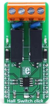
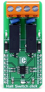
Hall Switch click is a magnetic field activated dual-relay Click board™. Hall Switch click has two high-quality relays, which are activated by the Hall-effect sensor: when the north pole magnetic field is introduced to the sensor, one of the relays will be activated; when the south pole magnetic field is introduced to the sensor, the other relay will be activated. Two high-quality compact relays allow switching of high voltages - up to 220V, so they can cut or establish a connection on the main side of the circuit.
This allows for the implementation of various applications activated by the magnetic field, such as the contactless switches, door, lids or tray position detecting switches, or other similar applications that require contactless switching of the relay contacts.
How does it work?
The main active element of the Hall Switch click is the AH1389, an ultra-sensitive dual output unipolar Hall Effect switch, from Diodes Incorporated. This IC utilizes Hall effect - a phenomenon in which the current flow, or rather - the path of the conductor electrons is affected by the magnetic field. Due to the fact that the path of the electrons is curved, a buildup of positive charges is formed on the opposite side of this path, and the voltage is generated. If a voltmeter is connected to the path perpendicular to the current path and the magnetic field, a voltage will be detected.
The AH1389 has the ability to detect both the north and south poles of the magnetic field. The magnetic field from the south pole magnet will pull the output 2 to a LOW (active) state, while the magnetic field from the north pole magnet will pull the output 1 to a LOW (active) state. The IC features several sections for the signal conditioning. It also provides the hysteresis for the output activation, to avoid erratic triggering. The magnetic field strength which activates outputs is about ±25 G, while the field strength under ±20 G will deactivate outputs, giving a hysteresis of typical 5 G. The positive and negative sign is used with respect to the magnet poles (north pole has a negative sign prefix).
The outputs of the AH1389 IC are routed to the operational amplifiers, which work as the inverting comparators. When the output of the AH1389 IC is activated - pulled to a LOW voltage level, the output from the comparator will be set to 5V. This will cause biasing of the BJT, allowing current flow through the relay coil, and thus forming a magnetic field necessary for closing the relay contacts. A Schottky diode across the relay coil prevents the reverse kickback voltage, which forms due to the inert nature of the coils. Activation of the relay coils is indicated by the red and blue LEDs, respectively.
Two outputs of the AH1389 IC are also routed to the mikroBUS pins: north pole output (1) is routed to the CS pin and the south pole output (2) is routed to the INT pin of the mikroBUS™ so that the status of the IC can be monitored by the MCU.
Two varistors are used to prevent voltage peaks when the load is connected or disconnected on the relay output contacts. The output contacts are further routed to the screw terminals, which allow up to 10A. However the relays allow up to 5A for 250V AC/30V DC, so the connected load should not exceed these power ratings.
 DO NOT TOUCH THE BOARD WHILE THE HIGH VOLTAGE IS APPLIED!
Note: Hall Switch click has exposed pins/pads. To stay safe, please take precaution when applying a high voltage to the click. The click is to be used by trained personnel only when operating with hazardous voltage levels.
Specifications
| Type |
Hall effect,Magnetic |
| Applications |
It can be used for applications activated by the magnetic field, such as the contactless switches, door, lids or tray position detecting switches, or other similar applications that require contactless switching of the relay contacts |
| On-board modules |
AH1389, an ultra-sensitive dual output unipolar Hall Effect switch, from Diodes Incorporated |
| Key Features |
Reliable contactless switching by the magnetic field, separate sensors for both south and north pole magnetic fields, high-quality compact OMRON relays, etc. |
| Interface |
GPIO |
| Input Voltage |
3.3V,5V |
| Click board size |
L (57.15 x 25.4 mm) |
Pinout diagram
This table shows how the pinout on Hall Switch click corresponds to the pinout on the mikroBUS™ socket (the latter shown in the two middle columns).
| Notes | Pin |  | Pin | Notes |
|---|
|
NC |
1 |
AN |
PWM |
16 |
NC |
|
|
NC |
2 |
RST |
INT |
15 |
S-P |
South pole |
| North pole |
N-P |
3 |
CS |
RX |
14 |
NC |
|
|
NC |
4 |
SCK |
TX |
13 |
NC |
|
|
NC |
5 |
MISO |
SCL |
12 |
NC |
|
|
NC |
6 |
MOSI |
SDA |
11 |
NC |
|
| Power Supply |
+3V3 |
7 |
3.3V |
5V |
10 |
+5V |
Power Supply |
| Ground |
GND |
8 |
GND |
GND |
9 |
GND |
Ground |
Onboard settings and indicators
| Label | Name | Default | Description |
|---|
| LD1 |
N |
- |
Relay 1 status LED, lights up when the north magnetic pole is applied |
| LD2 |
S |
- |
Relay 2 status LED, lights up when the south magnetic pole is applied |
| LD3 |
PWR |
|
PWR indication LED |
Software support
We provide a library for Hall Switch click on our Libstock page, as well as a demo application (example), developed using MikroElektronika compilers and mikroSDK. The provided click library is mikroSDK standard compliant. The demo application can run on all the main MikroElektronika development boards.
Library Description
The library carries two functions for poles control.
Key functions:
void hallswitch_setNpole(uint8_t state) - Set the state of N pole
void hallswitch_setSpole(uint8_t state) - Set the state of S pole
Examples Description
The application is composed of three sections:
- System Initialization - Initializes CS pin and INT pin as OUTPUT.
- Application Initialization - Initializes Driver init and turn OFF S pole and N pole.
- Application Task - (code snippet) - Turns S and N on and off every 500 ms.
void applicationTask()
{
 hallswitch_setNpole(_HALLSWITCH_POLE_ACTIVE);
 Delay_ms( 500 );

 hallswitch_setSpole(_HALLSWITCH_POLE_ACTIVE);
 Delay_ms( 500 );

 hallswitch_setNpole(_HALLSWITCH_POLE_NO_ACTIVE);
 Delay_ms( 500 );

 hallswitch_setSpole(_HALLSWITCH_POLE_NO_ACTIVE);
 Delay_ms( 500 );
}
The full application code, and ready to use projects can be found on our Libstock page.
Additional notes and information
Depending on the development board you are using, you may need USB UART click, USB UART 2 click or RS232 click to connect to your PC, for development systems with no UART to USB interface available on the board. The terminal available in all MikroElektronika compilers, or any other terminal application of your choice, can be used to read the message.
mikroSDK
This Click board™ is supported with mikroSDK - MikroElektronika Software Development Kit. To ensure proper operation of mikroSDK compliant Click board™ demo applications, mikroSDK should be downloaded from the LibStock and installed for the compiler you are using.
For more information about mikroSDK, visit the official page.