Besides these advanced technologies, the TMC5130 driver employs a set of other features: very high-power density - wide input voltage range and high output current, full output protection and diagnostics, highly efficient low RDSON output MOSFETs, integrated pulse generator for standalone operation, a SPI and simple STEP/DIR GPIO interfaces for driving the motor, and more. All these features allow the developing of a highly integrated and reliable step motor driving solution with outstanding performances. It can be used as a direct substitution for many complex motion controllers for various industrial motion control purposes, such as CNC, textile or sewing Machines, ATMs/Cash recyclers, pumps, valves, printers, scanners, medical devices, and many more.
How does it work?
Silent Step click uses the TMC5130 - the universal high voltage controller/driver for two-phase bipolar stepper motor, from the Trinamic company. As already mentioned, this device features many different features, which allow using the driver almost autonomously. There are two control interfaces: the SPI serial interface and the STEP/DIR interface. The SPI interface is used to write control information to the chip and read back status information. This interface must be used to initialize the parameters and modes necessary to enable driving the motor. The motion of the motor can be controlled by using the STEP and DIR signals, or through the SPI interface alone. Technologies, such stallGuard2™ - high precision sensorless motor load detection; spreadCycle™ - highly dynamic motor current control; stealthChop™ - extremely quiet operation and smooth motion, microPlayer™ - interpolation with 256 microsteps, help to achieve high autonomy and smooth motion of the driven motor, even by using the STEP and DIR input pins to set the direction and step propagation. The internal microstep table maps the sine function from 0° to 90°. Symmetries allow mapping the sine and cosine functions from 0° to 360° with this table.

The TMC5130 supports two motor driver control modes: STEP/DIR mode and SPI mode. STEP/DIR mode is also referred to as the legacy mode. The device is operated similar to other pin-driven step motor controllers/drivers – the step propagation is controlled by pulses on the STEP input, and the direction is determined by the DIR pin. In SPI mode, user has direct access to motor current sign and magnitude, by setting the parameters in DRVCTRL Register. All working parameters can be configured and controlled via the SPI interface in both modes, and also the power and thermal data can be provided back to the MCU for further analysis and optimization.
In STEP/DIR mode, the microPlyer STEP pulse interpolator brings the smooth motor operation of high-resolution microstepping to applications originally designed for coarser stepping and reduces pulse bandwidth. MicroPlyer produces 16 microsteps at 256x resolution, for each active edge on STP pin of the Silent Step click. For a better explanation, the diagram of the motor angle dependence on the step pulses is given:
The application may need to change the microstepping resolution to get the best performance from the motor. For example, on an CNC machine, high-resolution microstepping may be used for precision operations on a workpiece, and then full stepping may be used for maximum torque at maximum velocity to advance to the next workpiece. That is also possible, but attention should be paid to the exact moment of resolution changing, which should occur at or near positions that correspond to steps in the lower resolution.
The currents through both motor coils are controlled using choppers, which work independently of each other. There are two chopper modes available: a new high-performance chopper algorithm called spreadCycle and a proven constant off-time chopper mode. The constant off-time mode cycles through three phases: on, fast decay, and slow decay. The spreadCycle mode cycles through four phases: on, slow decay, fast decay, and a second slow decay. For more details about the chopper modes, phases and the parameters that are used for controlling the choppers, refer to the TMC5130 datasheet.
In order to achieve all the previously mentioned features working, the current through the motor coils have to be measured. Because of the high power output of the TMC5130, it is recommended to use the external shunt resistors. Therefore, the Silent Step click has onboard carefully selected, low-inductance type 0.1 Ohm shunt resistors. This minimizes measurement imperfections caused by the switching spikes from the MOSFET bridges for example and maximizes the efficiency of the TMC5130.
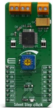
The STEP, DIR, SD_MODE, and SPI_MODE pins of the TMC5130 are directly routed to the mikroBUS™ pins PWM, INT, RST, and AN, and marked as STP, DIR, SDM, and SPM respectively. The logic levels of the digital I/O pins is easily adjustable by setting the desired voltage to the VCC_IO pin. Therefore, the interface logic level on the Silent Step click can be easily configured for 3.3 V or 5 V logic by moving VSEL jumper to the respective voltage, which allows both 3.3V and 5V MCUs to be interfaced with this Click board™.
The power supply for the connected bipolar stepper motor can be connected between the VM and GND inputs of the terminal. The connected voltage should stay within the range between 5V and 46V. The rest of the terminals allow bipolar stepper motor coils to be connected: A1 and A2 terminal inputs are used to connect the first coil, while the B1 and B2 inputs are used to connect the second motor coil.
Note that while driving the motor with higher currents, the TMC5130 might get warm, affecting its reliability. In that case, proper heat sinks should be used, or the driving current should be reduced.
Specifications
| Type |
Stepper |
| Applications |
This Click board™ is a perfect solution for building various applications that require precise and reliable stepper motor control, such as the CNC, textile or sewing Machines, ATMs/Cash recyclers, pumps, valves, printers, scanners, medical devices, and many more |
| On-board modules |
TMC5130, a highly integrated bipolar step motor power driver, with the UART interface, from the Trinamic company |
| Key Features |
StallGuard2™, coolStep™, spreadCycle™, and microPlayer™ advanced technologies, full output protection and diagnostics, wide input voltage range and reasonably high currents, highly efficient output MOSFETs, etc. |
| Interface |
GPIO,SPI |
| Click board size |
M (42.9 x 25.4 mm) |
| Input Voltage |
3.3V,5V |
Pinout diagram
This table shows how the pinout on Silent Step click corresponds to the pinout on the mikroBUS™ socket (the latter shown in the two middle columns).
| Notes |
Pin |
 |
Pin |
Notes |
|---|
| Ramp generator mode selection input |
SPM |
1 |
AN |
PWM |
16 |
STP |
Step trigger IN |
| Communication mode selection input |
SDM |
2 |
RST |
INT |
15 |
DIR |
Motor direction IN |
| Chip Enable |
CS |
3 |
CS |
RX |
14 |
NC |
|
| SPI Clock |
SCK |
4 |
SCK |
TX |
13 |
NC |
|
| SPI Data Out |
SDO |
5 |
MISO |
SCL |
12 |
NC |
|
| SPI Data In |
SDI |
6 |
MOSI |
SDA |
11 |
NC |
|
| Power Supply |
3.3V |
7 |
3.3V |
5V |
10 |
5V |
Power supply |
| Ground |
GND |
8 |
GND |
GND |
9 |
GND |
Ground |
Onboard settings and indicators
| Label |
Name |
Default |
Description |
|---|
| PWR |
PWR |
- |
Power LED Indicator |
| TB1 |
VM |
- |
The external power supply connector |
| TB2 |
A1,A2 |
- |
Stepper motor coil A connector |
| TB3 |
B1,B2 |
- |
Stepper motor coil B connector |
| JP1 |
VSEL |
Left |
Logic voltage level selection: left position - 3.3V; right position - 5V |
Silent Step click electrical specifications
| Description |
Min |
Typ |
Max |
Unit |
|---|
| External power supply voltage |
5 |
- |
46 |
V |
| I/O supply voltage |
3 |
- |
5.25 |
V |
| Current limit (RMS) per channel |
- |
- |
2 |
A |
Software Support
We provide a library for the Silent Step click on our LibStock page, as well as a demo application (example), developed using MikroElektronika compilers. The demo can run on all the main MikroElektronika development boards.
Library Description
Library carries everything needed for stepper motor control including speed and acceleration setup. Library is also adjustable to working on different amount of ticks per second, also speed and acceleration can be provided in float format. Buffer used for movement calculation is defined by user so this library can be adjusted for MCUs with very limited RAM resources. Library also performs a motor control by using SPI driver. Check documentation for more details how to use it.
Key functions:
uint8_t stepper11_setSpeed( float minSpeed, float maxSpeed, float accelRatio, T_STEPPER11_OBJ obj ) - Setup motor speed.uint8_t stepper11_setRoute( const uint8_t direction, uint32_t steps, T_STEPPER11_OBJ obj ) - Setup new route.void stepper11_start( T_STEPPER11_OBJ obj ) - Start motor movement.
Examples description
The application is composed of three sections :
- System Initialization - Initializes all GPIO pins found on Silent Step click and timer to 1ms interrupt.
- Application Initialization - First segment initializes driver and stepper control. Second segment setup movement limits, maximum and minimum speed, and acceleration ratio. Third segment performs a mode and microstep selection and setup new route which will be called from application task.
- Application Task - (code snippet) - Sequentialy moves motor. Every part of sequence executes movement until the end, but with different speed, direction and microstep resolution.
void applicationTask()
{
    stepper11_setSpeed( 250.0, 250.0, 0.1, (T_STEPPER11_OBJ)&myStepper );
    stepper11_setRoute( _STEPPER11_DIR_CW, 200, (T_STEPPER11_OBJ)&myStepper );
    if (stealthCheck == _STEPPER11_STEALTH_DIS)
    {
        stepper11_setMicrostepResolution( _STEPPER11_SPREAD_FULL_STEP );
    }
    stepper11_start( (T_STEPPER11_OBJ)&myStepper );
    while ( myStepper.status.running )
    {
        stepper11_process( (T_STEPPER11_OBJ)&myStepper );
    }

    stepper11_setRoute( _STEPPER11_DIR_CCW, 200, (T_STEPPER11_OBJ)&myStepper );
    stepper11_start( (T_STEPPER11_OBJ)&myStepper );
    while ( myStepper.status.running )
    {
        stepper11_process( (T_STEPPER11_OBJ)&myStepper );
    }
    Delay_ms( 200 );

    stepper11_setSpeed( 10.0, 500.0, 0.1, (T_STEPPER11_OBJ)&myStepper );
    stepper11_setRoute( _STEPPER11_DIR_CW, 200, (T_STEPPER11_OBJ)&myStepper );
    if (stealthCheck == _STEPPER11_STEALTH_DIS)
    {
        stepper11_setMicrostepResolution( _STEPPER11_SPREAD_HALF_STEP );
    }
    stepper11_start( (T_STEPPER11_OBJ)&myStepper );
    while ( myStepper.status.running )
    {
        stepper11_process( (T_STEPPER11_OBJ)&myStepper );
    }
    Delay_ms( 2000 );
}
In addition to library function calls example carries necessay Timer ISR and Timer initialization. Check Timer initialization setings and update it according to your MCU - Timer Calculator.
The full application code, and ready to use projects can be found on our LibStock page.
Additional notes and informations
Depending on the development board you are using, you may need USB UART click, USB UART 2 click or RS232 click to connect to your PC, for development systems with no UART to USB interface available on the board. The terminal available in all MikroElektronika compilers, or any other terminal application of your choice, can be used to read the message.
mikroSDK
This Click board™ is supported with mikroSDK - MikroElektronika Software Development Kit. To ensure proper operation of mikroSDK compliant Click board™ demo applications, mikroSDK should be downloaded from the LibStock and installed for the compiler you are using.
For more information about mikroSDK, visit the official page.
Resources
Downloads