|
|
| |
|
 | Search: |
|
|
 |

|
|
DC MOTOR click is a DC motor driver board in the mikroBUS form factor. It features the DRV8833RTY H-Bridge motor driver, 74HC4053 multiplexer and two screw terminals. The 74HC4053 IC is incorporated into the design so that the motor can be run using only the one PWM line available on the mikroBUS socket. DC MOTOR click communicates with the target board via SELECT1, SELECT2 and nSLEEP control lines; PWM input line and nFAULT feedback line. The board is designed to use either a 3.3V or 5V power supply. It can be powered from the mikroBUS socket, or externally through the CN2 screw terminals (3-10V). It is limited to a 0.9A driving current and has a 0.22R current sense resistor. The motor is connected to the CN1 screw terminal. |
|
|
|
|
 |

|
|
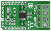
DC MOTOR 2 click carries the TB6593FNG driver IC for direct current motors. With two pairs of screw terminals (power supply and outputs), the click board can drive motors with voltages from 2.5 to 13V (output current of up to 1.2 amps with peaks up to 3.2 amps). The PWM signal drives the motor while the IN1 and IN2 pins provide binary direction signals that set the direction of the motor (clockwise or counter clockwise), or apply stop or short brake functions. Stop mode cuts off the power supply so the motor continues spinning until it runs out of momentum. Short break brings it to an abrupt stop. |
|
|
|
 |

|
|
DC MOTOR 3 click is a mikroBUS™ add-on board with a Toshiba TB6549FG full-bridge driver for direct current motors. The IC is capable of outputting currents of up to 3.5 A with 30V, making it suitable for high-power motors.
Two pairs of screw terminals are positioned on the top of the board. One is for bringing an external power supply; the other is for connecting a motor.
TB6549FG has four operating modes: clockwise, counter-clockwise, short brake and stop. The operating mode is configured through IN1 and IN2 pins. A separately controlled standby mode is also available.
For safety, the TB6549FG IC incorporates overcurrent protetciont and a thermal shutdown circuit.
The click communicates with the target MCU through the mikroBUS™ PWM pin, with additional functionality provided by IN1, IN2 and SLP pins (in place of default mikroBUS™ AN, RST and CS pins). Designed to use a 3.3 power supply only. |
|
|
|
 |
|
|

