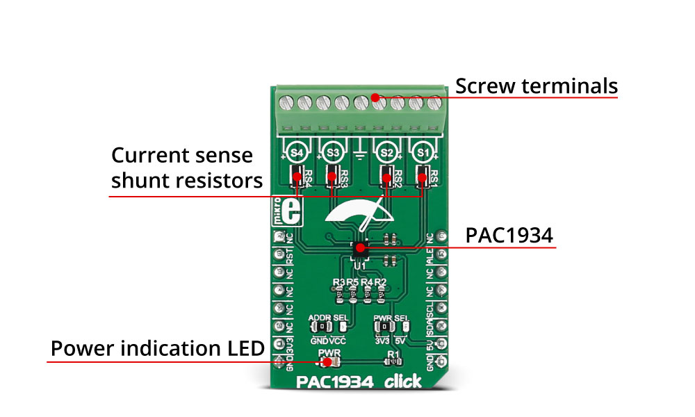
PAC1934 click carries the PAC1934 four channel DC power/energy monitor from Microchip. The click is designed to run on either 3.3V or 5V power supply. It communicates with the target microcontroller over an I2C interface.
How the click works
There are four 4-Terminal current sense shunt resistors connected to the current sense amplifier (in the chip). Electricity is brought to shunts via screw terminals. Middle screw connector is GND which can be used for bus voltage monitoring.
This click enables energy monitoring with integration periods from 1 mS up to 36 hours or longer. Bus voltage, sense resistor voltage, and accumulated proportional power are stored in registers for retrieval by the system master or Embedded Controller.
PAC1934 energy monitor features
The PAC1934 is a four channel bi-directional high-side current-sensing device with precision voltage measurement capabilities, DSP for power calculation, and a power accumulator. It measures the voltage developed across an external sense resistor (VSENSE) to represent the high-side current of a battery or voltage regulator. The PAC1932/3/4 also measures the SENSE1+ pin voltages (VBUS).

Specifications
| Type |
Measurements |
| Applications |
Power management systems, embedded applications, servers, personal computers, etc. |
| On-board modules |
PAC1934 four channel energy monitor from Microchip |
| Key Features |
1% power measurement accuracy over a wide
dynamic range, alert feature on accumulator overflow and conversion complete, that could be enabled |
| Interface |
I2C |
| Input Voltage |
3.3V or 5V |
| Click board size |
M (42.9 x 25.4 mm) |
Pinout diagram
This table shows how the pinout on PAC1934 click corresponds to the pinout on the mikroBUS??? socket (the latter shown in the two middle columns).
| Notes | Pin |  | Pin | Notes |
|---|
|
NC |
1 |
AN |
PWM |
16 |
NC |
|
| Reset |
RST |
2 |
RST |
INT |
15 |
ALE |
Alert pin |
|
NC |
3 |
CS |
TX |
14 |
NC |
|
|
NC |
4 |
SCK |
RX |
13 |
NC |
|
|
NC |
5 |
MISO |
SCL |
12 |
SCL |
I2C clock |
|
NC |
6 |
MOSI |
SDA |
11 |
SDA |
I2C data |
| Power supply |
+3.3V |
7 |
3.3V |
5V |
10 |
+5V |
Power supply |
| Ground |
GND |
8 |
GND |
GND |
9 |
GND |
Ground |
Jumpers and settings
| Designator | Name | Default Position | Default Option | Description |
|---|
| JP1 |
PWR.SEL. |
Left |
3V3 |
Power Supply Voltage Selection 3V3/5V, left position 3V3, right position 5V |
| JP2 |
ADDR.SEL. |
Left |
20h |
I2C Address select - Left position 20h, Right position 3Eh |
LEDs, Buttons, Switches, Connectors, etc.
| Designator | Name | Type (LED, BUTTON...) | Description |
|---|
| LD1 |
PWR |
LED |
Power indication LED |
Programming
Code examples for PAC1934 click, written for MikroElektronika hardware and compilers are available on Libstock.
Code snippet
The following code snippet shows how to measure Current, Voltage, Power and Energy using the PAC1934 library.
01 char txt [30];
02     float readValue;
03     PAC1934_sendCommand (_PAC1934_REFRESH_CMD);
04     delay_ms (200);
05
06    readValue = PAC1934_measureVoltage(4);
07     FloatToStr(readValue, txt);
08     LOG ("VBUS 4:      ");
09     LOG (txt);
10     LOG (" Vrn");
11
12    readValue = PAC1934_measureCurrent(4);
13     FloatToStr(readValue, txt);
14     LOG ("Current 4:   ");
15     LOG (txt);
16     LOG (" mArn");
17
18    readValue = PAC1934_measurePower(4);
19     FloatToStr(readValue, txt);
20     LOG ("Power 4:     ");
21     LOG (txt);
22     LOG (" Wrn");
23
24    readValue = PAC1934_measureEnergy(4, 8);
25     FloatToStr(readValue, txt);
26     LOG ("Energy 4:    ");
27     LOG (txt);
28     LOG (" Jrn");
29
30    LOG ("____________________rn");
31     delay_ms (10000);

